Injection System Stuff (Updated March 2018)
OK, I know there's lots of information around the internet and in learned tomes about how the Rover V8's Lucas/Bosch fuel injection works but as you're here, indulge me while I put my own, non-too technical stamp on it (I hope!). So, first things first. A petrol engine works by compressing a certain volume of air, mixed with a certain volume of petrol, into a very small space. This compressed mixture is then ignited (by a spark plug) and as it burns it expands. Since the mass of metal that comprises the engine is containing it, the expanding gas released by the burning fuel/air mixture takes the easiest way out, that is, by pushing the piston down the cylinder, applying leverage to the crankshaft and making it turn. With me so far? Good. Right, people with very large foreheads worked out a good century back that the optimum ratio of air to fuel is somewhere around 12:1 to 14:1 - in other words, 12-14 parts of air to one part of fuel (the first number would be called a 'rich' mixture as there's less air per molecule of fuel and the latter a 'weak' mixture for the opposite reason). Now that seems like a very narrow window and indeed it is: too much air or too much fuel and the mixture becomes unignitable. There's a narrow band each end of the 12-14:1 range where it will still ignite but be less efficient, but we'll gloss over that for the purposes of simplicity. So, if we could measure how much air was being drawn in we could add just the right amount of fuel. As it happens we know how much air is being drawn in: it's the rated capacity of the engine divided by the number of cylinders and in the case of the Rover engine that's about 3500cc and 8 cylinders (unless you have a larger capacity RV8 of course...). So each intaking stroke of each piston sucks in about 437cc of air. That would mean that for an average mixture of 13:1 (known as the 'Stoichiometric' ratio) you would need to add 33.5cc of petrol (per cylinder, remember). Now air is funny stuff. As you get further above the surface of the planet it gets thinner, i.e. there's less 'density' to it. This also happens on a warm day. Which means you need to also know what the air temperature is and how much air is in reality being drawn in. On top of this variable air there's also the temperature of the engine itself. Obviously it's more or less cold when you start but then it gets hotter, partly from the heat of the combusting mixture in each cylinder, partly from friction of all the moving parts slipping, sliding and rolling about each other. Over time and assuming the designers have provided a suitable temperature regulating mechanism (circulating water and a radiator fan to you, chief), the engine will eventually reach a temperature equilibrium of somewhere around 90 degrees Centigrade (I don't know what that is in Fahrenheit, I wasn't born until the 1960s!). OK, so, we've got our engine warm, we know how warm the air is and how much of it we've sucked in and we can calculate how much fuel we need to add to each cylinder. We need to modify the calculation further though, because under steady cruise conditions the engine will run happily with a slightly weaker (or 'leaner') mixture, whereas under hard acceleration it benefits from a bit more fuel per known volume of air (a 'richer' mixture). The final thing we could really do with knowing is how fast the engine is spinning, because obviously the faster it spins the more often we have to add a glug of fuel to each cylinder. If we had means of measuring all the foregoing parameters we'd be most of the way to controlling our fuelling... and indeed the Lucas/Bosch system does just that. It uses an Airflow Meter (AFM) to, believe it or not, measure the air flow. This takes the form of a duct through which all the air has to pass on its way to the cylinders. In the duct is a pivoting flap which is kept closed by a constant-force spring (think mainspring of a clock). As the intaking pistons draw the air through the duct the flap is forced to move against the spring and this movement is measured electronically. There's also a sensor sited in the duct to measure the incoming air temperature (the Intake Air Temperature Sensor or IATS). A further sensor (the Coolant Temperature Sensor, CTS) screwed into the inlet manifold measures the cooling water temperature, so now we have three of our unknowns. How fast is the engine spinning? Well, that's taken care of by detecting the trigger pulses that energise the ignition coil to fire the spark plugs. Similarly, the 'enthusiasm' of the driver is detected by a sensor on the throttle mechanism (the Throttle Potentiometer, TPS or 'pot' for short). This detects if the driver's foot is holding a constant position or has suddenly been planted, demanding acceleration and thus more fuel. So, now we know all the parameters affecting our fuelling demand, we need to get the fuel from the tank into the cylinders. As the engine spins faster and faster, the amount of time available to squirt the required volume of fuel in gets shorter and shorter. In order to speed things up, a high-pressure fuel pump is used which draws petrol from the tank and pumps it around a loop of pipe, known as the fuel rail. When the pressure in the rail reaches about 2.2 Bar (35 lbs/sq. in. or so) a spring-loaded diaphragm lifts and allows the fuel to bleed from the rail, back to the tank. This prevents excessive heat soak into the fuel as it sits waiting to be used (altering the density of it and messing up our calculations!). So a constant reserve of fuel is available close to the inlet manifold. Eight fuel injectors are fitted into the manifold, adjacent to the inlet valve for each cylinder. The injector comprises a spring-loaded needle (pintle) that keeps the fuel outlet closed until it is retracted against spring pressure by an electrical pulse. The principle is that as the inlet valve opens, the injector 'fires' for a brief period (thousandths of a second!) allowing the high-pressure fuel to pass through the injector and be drawn into the cylinder with the inrushing air. In a modern engine each injector is fired in sequence, but this is where the Lucas/Bosch system differs, in that ALL FOUR injectors on each 'bank' of cylinders is connected in parallel and fired at the same time. In practice this means that the three cylinders adjacent to the intaking one also receive a spray of fuel, but the the back of their CLOSED inlet valves. Thus there is always an amount of fuel (atomised by the spray action of the injectors) wafting around inside the inlet tracts. It must surely lead to an imbalance of the fuel taken by each cylinder but it seems to work so there's no point worrying about it! In effect what happens is that the injectors fire left-right-left-right-left so, and this is an interesting point, there's no need to 'time' the injection as there is in a modern 'sequential' system which uses a crank position sensor to know when to inject which cylinder. That additional bit of complexity is absent in the Lucas/Bosch system. You could effectively say that each bank of four injectors forms one huge injector and in principle you could do just that, have one injector per bank. To prove this works, some cars (notably small family hatchbacks!) have for years used a single injector in the inlet manifold doing effectively the same as the RV8 system, i.e. one injector serves whichever cylinder is intaking at any time... but I digress, as Ronnie Corbett might have said. Anyway, that's the basic 'modus operandi' of the fuel injection: measure all the parameters, calculate the fuel requirement, open the injectors for long enough to let that amount of fuel pass. Modify that time period according to engine speed, throttle position, coolant and air temperature. Ready for a break? Yep, me too.
As I mentioned, the injector 'open' time is measured in milliseconds. Obviously to perform a dynamic calculation of fuel requirement needs a computer (or Electronic Control Unit) and that of the RV8's injection is known as the 4CU. So it's a 4CU ECU, if you like. Bearing in mind it was developed in the early 1980s, there is no 'Intel inside'. This was the early days of home computers and just as with Clive Sinclair's products, Lucas had to commission a special set of integrated circuits from Ferranti. The principle of analogue-to-digital conversion was still in its infancy so the 4CU is largely an 'analogue' computer, that is it takes currents and voltages from the various engine sensors and adds them together, takes them away and divides by the number it first thought of, as it were. Unlike a modern 'closed-loop' injection system the RV8's does not measure the exhaust gases to detect incorrect fuelling (actually, some versions of it did but they mostly went to the USA and good riddance to them :D). Nor does it incorporate a fuelling 'map' where it can look up all combinations of load, speed, temperature etc. to arrive at an injector 'period'. Essentially it hazards a good guess, I suppose you could say, and in that respect it's better than a traditional carburettor which could be well out of adjustment - let's not forget that the major driving force behind the introduction of fuel injection to cars was emissions control - but it lacks the precision of a modern, closed-loop injection system. The 4CU cannot be 'remapped' or 'chipped' as it contains no software or firmware, although it can be tweaked and tuned to better match the particular state of tune of the engine it serves... but it's not something you can do easily at home, not that it stops people trying. Including me. While we're on about it, I've played with enough RV8 injection systems to be able to say that you can't just swap ECUs and Airflow Meters around willy-nilly as a way of diagnosing a fuelling fault. There were differences between the Range Rover and the Rover SD1, for example; the RR engine was tuned for more torque but less power and consequently has differing fuel requirements to the revvier, more powerful SD1 Vitesse engine. And then there are the 'hot' RV8s fitted to some TVR Wedges! On the plus side, Ive never seen an ECU fault that would damage another car's system if it was temporarily fitted for test purposes. So swap away; it may be a quick way to prove a dead ECU, but don't be surprised if the 'faulty' car when fitted with the ECU from a known-good 'test' car still runs like a bag of spanners. It's far to say that MOST OF THE TIME an apparent fault with the injection system will not be due to a faulty system component - or if it is, it'll usually be the less expensive bits that fail, such as the coolant temperature sensor. Granted, age is starting to take a toll but the Lucas/Bosch system is fundamentally reliable. Which is more than can be said for some of the people who try to repair or adjust them...
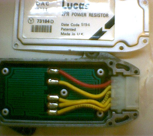
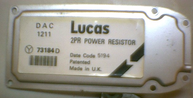
Ever wondered what was inside the Injector Power Resistor module?
Not much, actually! The resistors are formed by copper tracks on the circuit board; you can see them meandering around on the lower picture. The 2PR module is generally reliable; any problems tend to be related to the connector block or the wiring loom connector. Replacement crimp terminals are easily obtainable (try Vehicle Wiring Products) to allow a damaged or corroded connector to be repaired.
Two views of the larger-bore Jaguar airflow meter. The black mounting bracket and the alloy collar for the outlet air hose were fabricated by me. Poor picture quality due to the cheapo digital camera I had at the time!
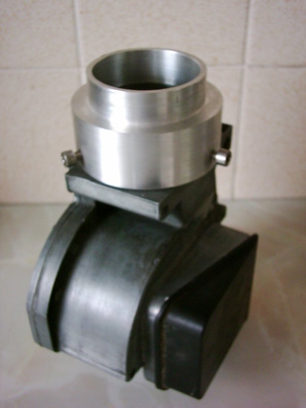
The airflow meter is a precision unit, but it's not actually THAT complicated to work on. Whilst I don't advocate that the AFM should be taken to bits for the hell of it, if you're going to do it, you may find my stripdown sequence useful...
I decided to have a crack at building an injection system to my own specification. That is to say, an attempt to optimise what I already had rather than an aftermarket ECU and associated sensors. There are those who insist that the Lucas system can't be tuned for much improvement, but several successful racers since the 1980's can't all be wrong!
Now I don't claim to be any sort of expert, but luckily I had a chat with Mark Adams, who is. He told me that the airflow meter would have been matched to the rest of the system and that NCK stamped their engine number on it. Whether they did or not I can't say, but my car had had its AFM replaced at some stage so it was almost certainly not optimised. Further, I'd replaced it with the Jaguar unit and merely adjusted it by trial and error to get what I thought was the best compromise - hardly a scientific way to optimise anything!
Mark suggested that the Jag AFM would tend to cause the mixture to be too lean. I pondered whether the quickest fix was to throw in more fuel :-D A search on Ebay turned up a guy selling brand new Jaguar fuel injectors in sets of 6. The maximum flow rate was some 40cc a minute more than the 180cc of the standard injectors, a worthwhile increase. I emailed him to ascertain that he could supply me with 8 and ended up getting a full set for less than £60 - well worth a fiddle, I thought!
For some obscure reason I convinced myself that NCK hadn't done any porting work on the inlet manifold and decided to have a go at opening the ports out on a spare manifold that I had. This proved to be quite easy but rather tedious and messy. Then I took the injection system off the car and discovered that, of course, NCK had opened the ports out - quite radically, in fact!
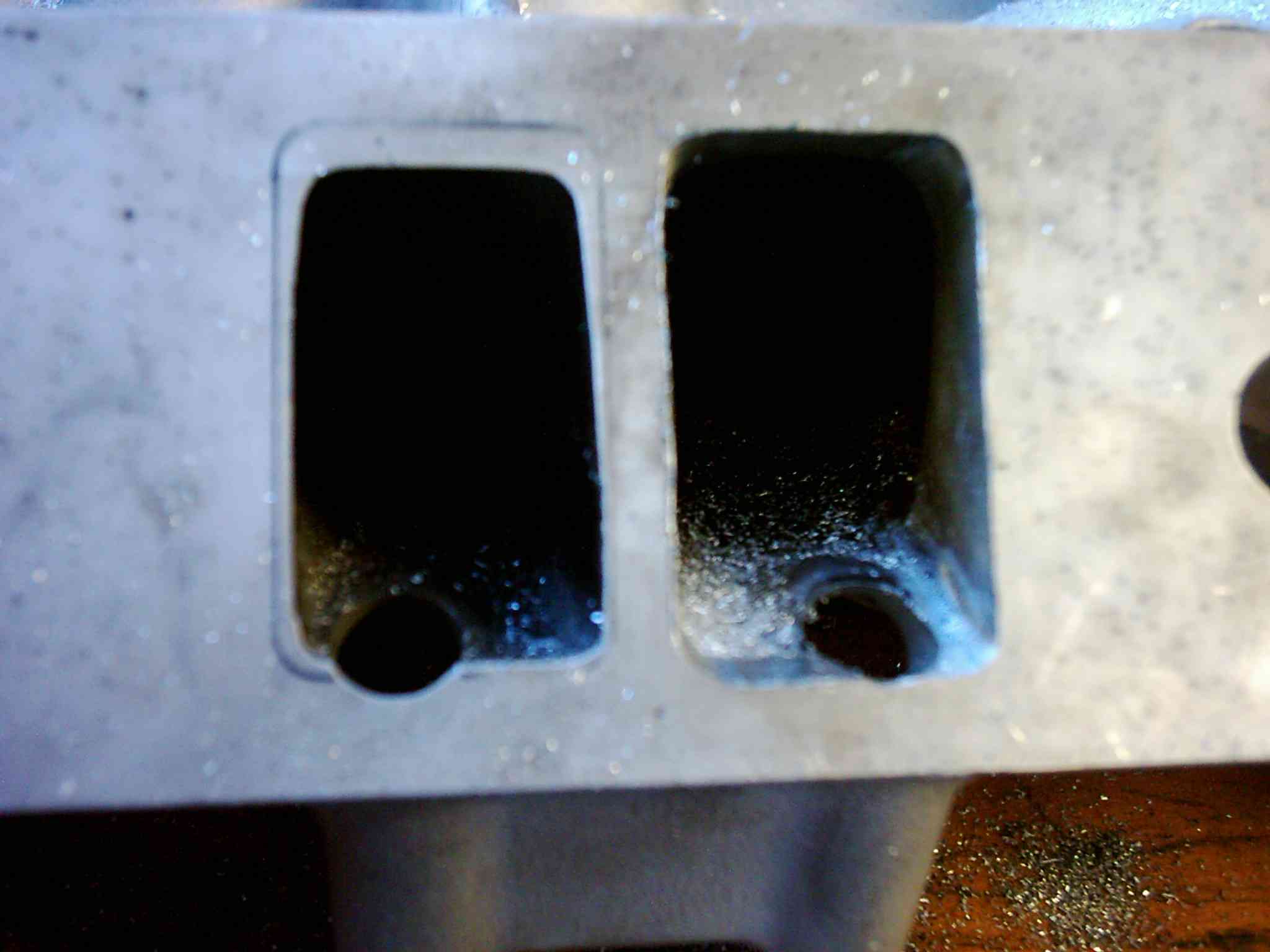
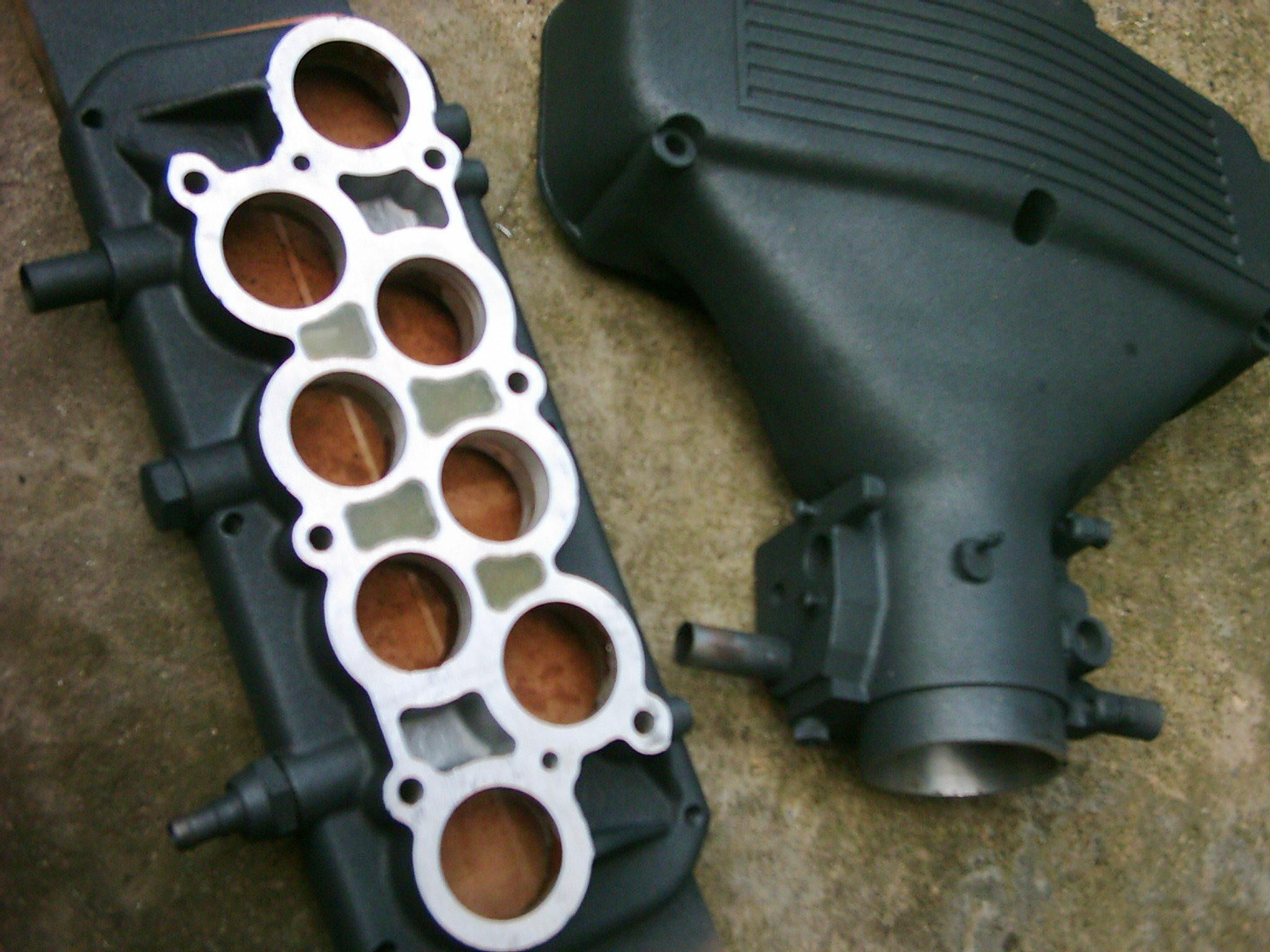
NCK's porting work (at left) compared with a standard manifold:
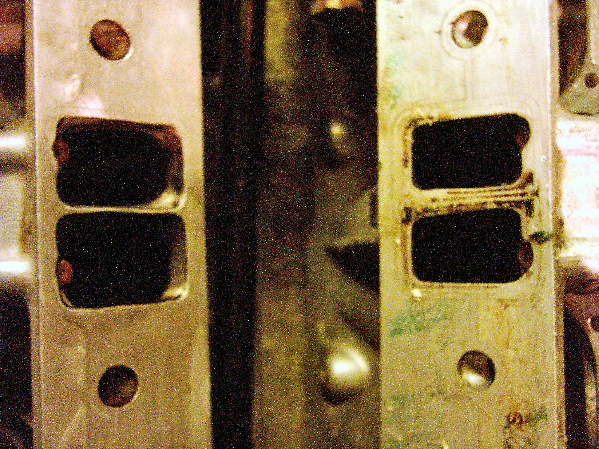
... and my first attempt at porting (on the right); outline round port at left is taken from the gasket...
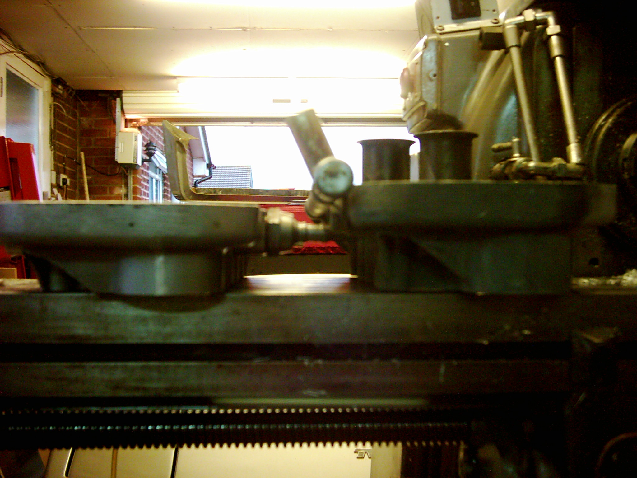
From discussions I'd had with various people in the Wedge community I knew that another worthwhile mod. was the addition of an insulator between the trumpet base and the inlet manifold. This reduces heat soak into the inlet tracts and should allow a cooler, denser air charge. Of course it would also add the thickness of the insulator to the inlet tract length, so I opted to shorten the trumpets by an appropriate amount to compensate. This has the added benefit of increasing the gap between the centre four trumpets and the inside of the plenum chamber top, apparently allowing better airflow at high rpm. Then another issue surfaced; that of under-bonnet clearance. Another few millimetres might just be enough to prevent the bonnet closing! I decided to mill the bottom of the trumpet base down by the thickness of the insulator, which would maintain the port lengths whilst avoiding clearance problems. Of course the shortened trumpets would now change the engine response, but I had plenty of spare trumpets if I didn't like it!
Plenum insulator machined and being tried for fit:
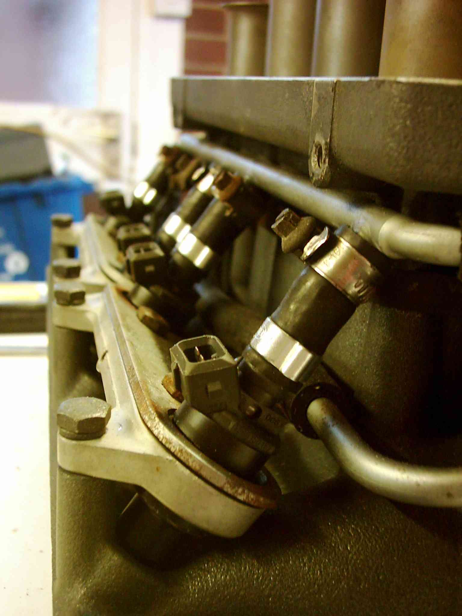
Bank of new injectors installed:
Shortened trumpet base on left, with a standard item for comparison:
The castings were also tidied-up a little to get rid of casting flash, Land Rover logos etc., and the parts given a coat of what Halfords call 'metallic black' but what looks more like graphite grey to me (Edit March 2013: this paint is actually good stuff, very hard-wearing!):
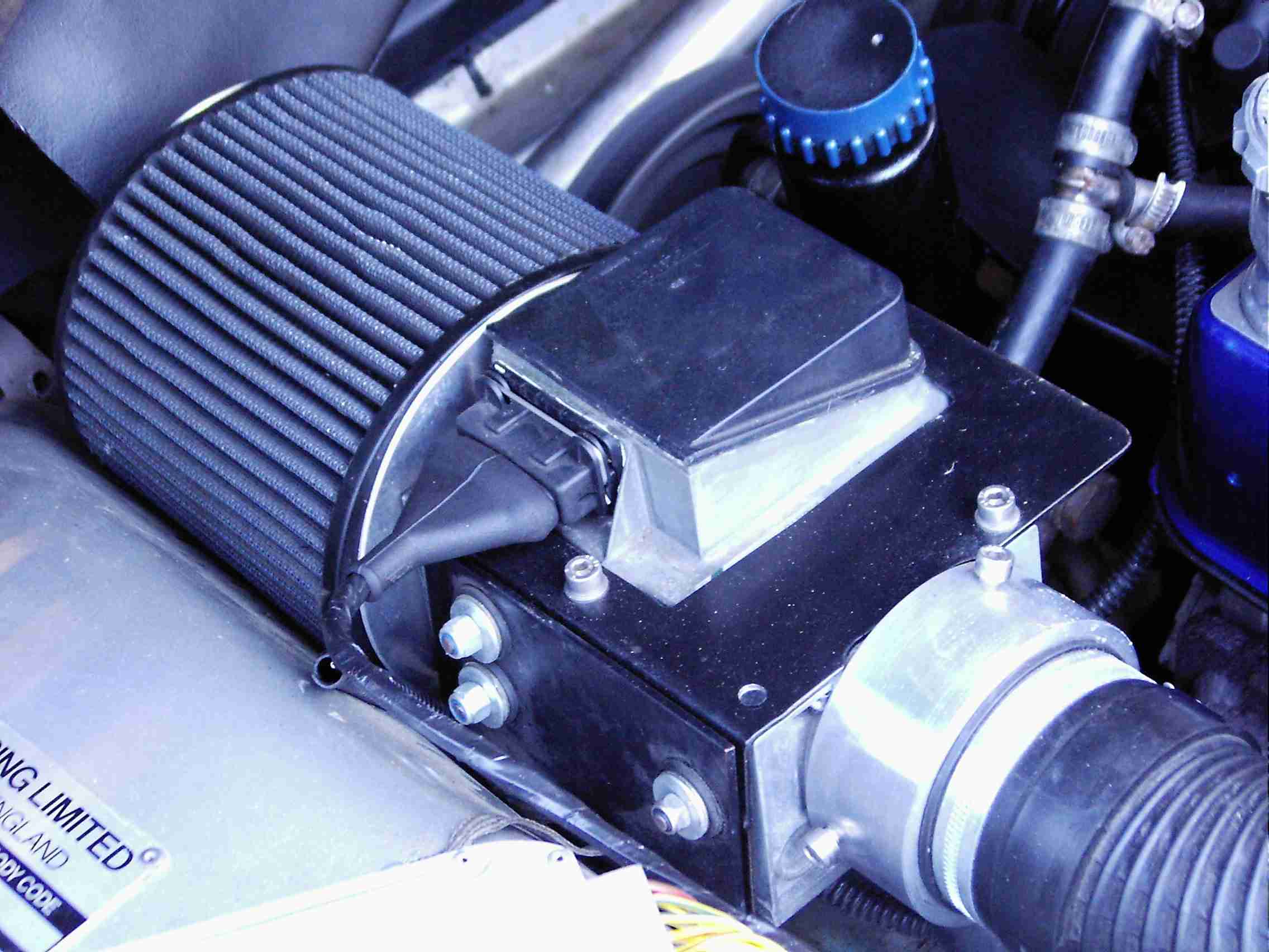
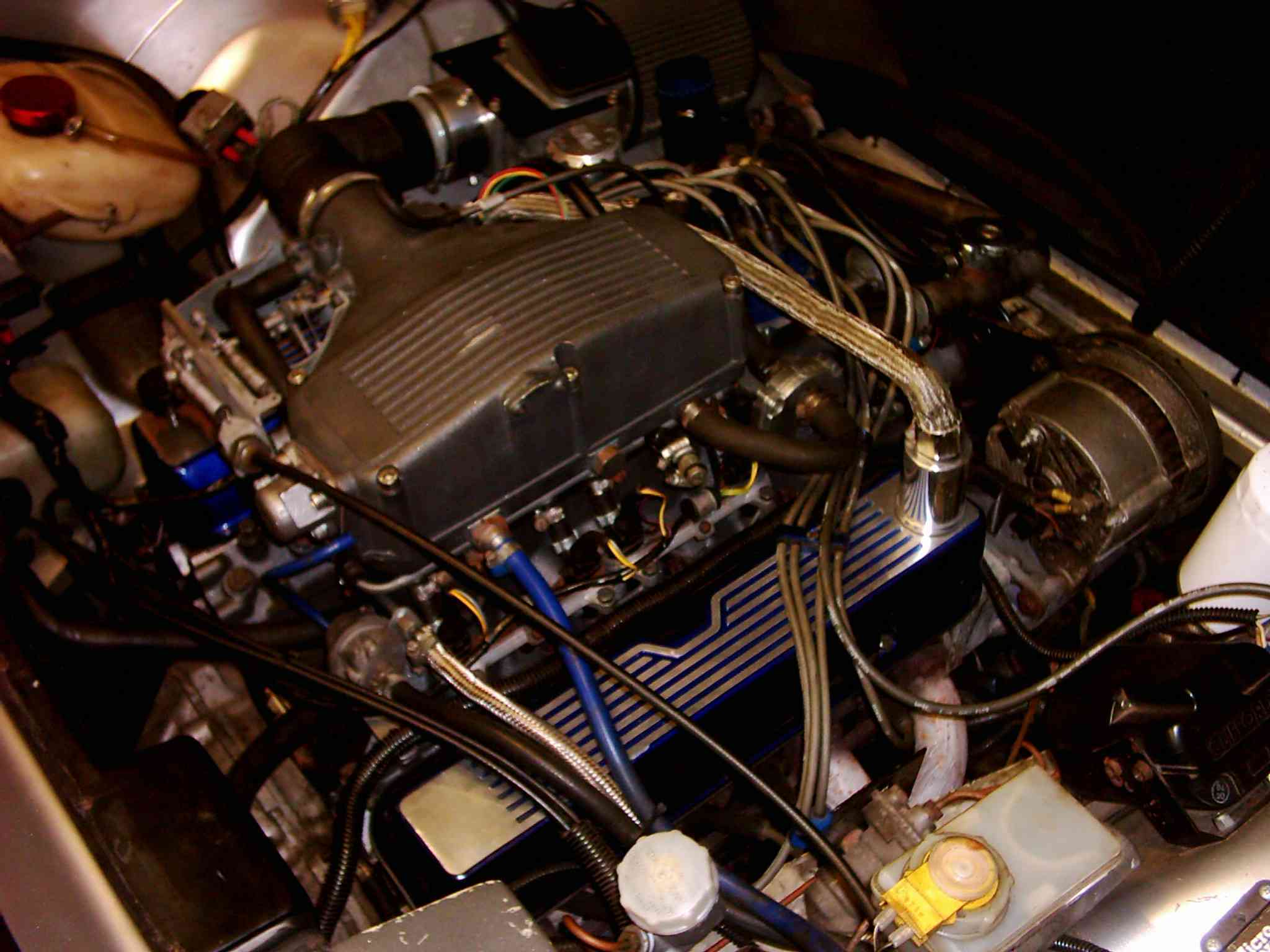
One possible modification is to bore out the throttle body to accept a larger-diameter throttle plate: another way that has also been implemented (and one which I fancy trying) is to chop off the existing throttle body, weld on a square plate suitably drilled to accept the throttle body from another car.... and it so happens that there's a Jaguar unit that looks very promising! Watch this space ... in the meantime, this is what my engine bay looks like with the 'project' injection system installed:
...and the proof of the pudding of course is on the dyno, where with my guesstimated injection system 'set up' by the seat of my pants the car made 256bhp at the flywheel, with 280lb.ft. of torque. However the most pleasing part was the air:fuel ratio, which looked like this (204bhp being the figure at the wheels):
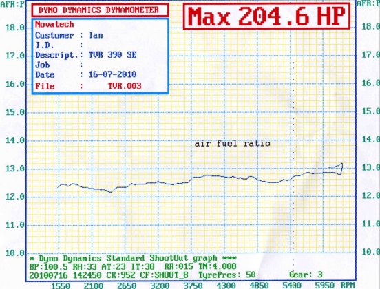
I guess the next logical step is to reinstate the NCK-worked inlet manifold etc. and see how many more of the claimed 275bhp might be available ;)