The TVR/ Rover V8 drooling page... :-D
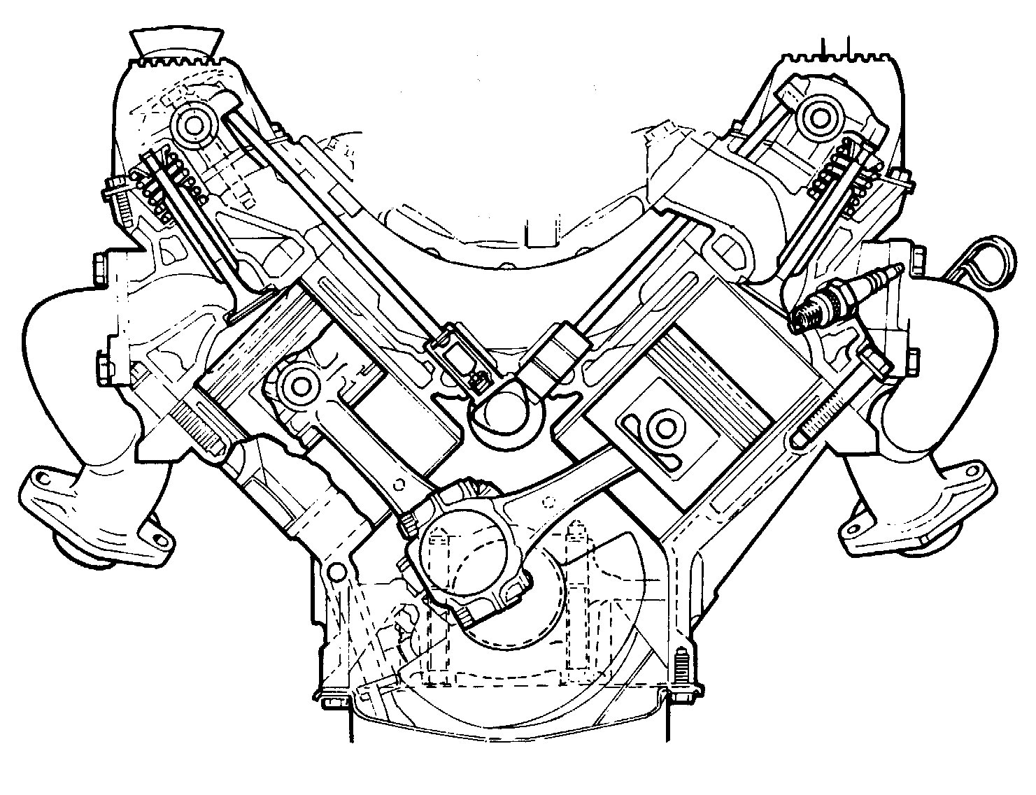
Cutaway view of the RV8:-
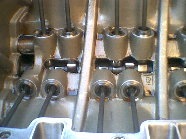
View of the inside of the V8 in my TVR, showing camshaft, followers, pushrods.
This is how clean the inside of an engine should be! Grinder marks around the edges of casting show where rough edges of metal were removed to improve the oil drainage. One modification that is often mentioned is to drill a hole through the front wall of the casting (the far left in this picture), sloping down towards the crank sprocket that drives the timing chain; the idea being that some of the stray oil in the valley is diverted to the chain which helps prolong its life. I hadn't heard about the hole when I had my engine stripped. A previous owner had replaced the standard sprockets and chain with a duplex version plus a 'vernier' adjustable cam sprocket, however the remainder of the valve train is standard RV8 with hydraulic followers, solid pushrods and non-adjustable rockers.
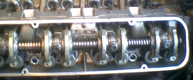
View of the valvegear. In both pics you can make out the porting work performed by NCK when they created the 3.9L:
The previous owner of my car had fitted an aluminium gearknob. I found its polished dome a bit slippery so I looked around and found this alternative on Ebay:
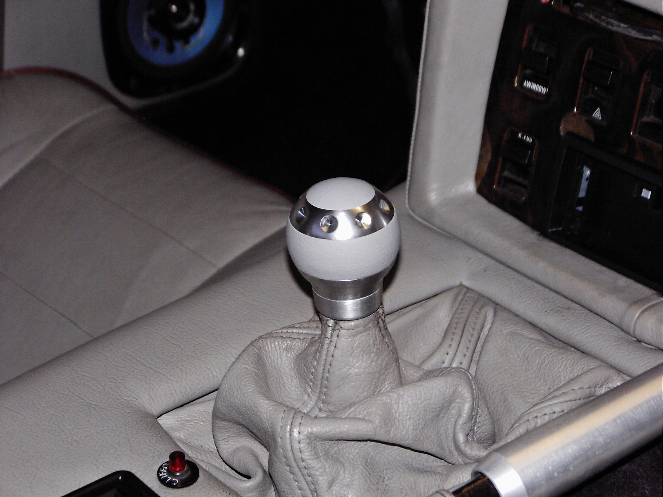
Not too convinced about the ring of dimples in it but the leather inserts do offer more grip - and it's more securely attached to the stick than was the previous one, which had a habit of unscrewing itself! I think the new one is by Momo but don't quote me; for 12 quid I thought it was worth a punt.
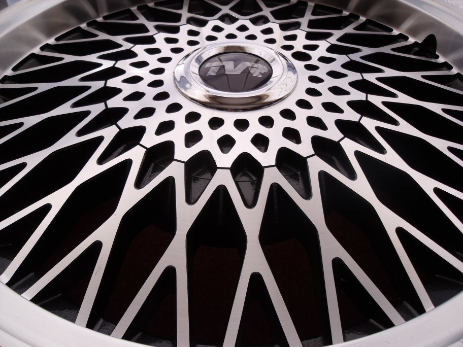
My latest acquisitions: a new set of wheels for the old bus! In about 1990 TVR produced a limited run of cars badged '350SE' - essentially a 350i shell with a 3.9L engine: whether this was an off-the-line standard Landrover unit or tuned to be similar to the engine from the 390SE, I don't know but suspect the former. To further enhance the model a different type of wheel was fitted from the usual 'spoked' alloy. The story goes that when Peter Wheeler was dismantling TVR upon his retirement in 2004, various parts that had lain around the factory were sold off, and this set of wheels was acquired by one of the growing band of TVR 'specialist' companies. They were subsequently sold and fitted to a car for about 500 miles then removed for reasons unknown. They then passed to a new owner who never used them and from whom I acquired them, for not significantly more than it would have cost me to have the existing set on the car refurbished (which they badly need!). Here they are cluttering up my lounge:
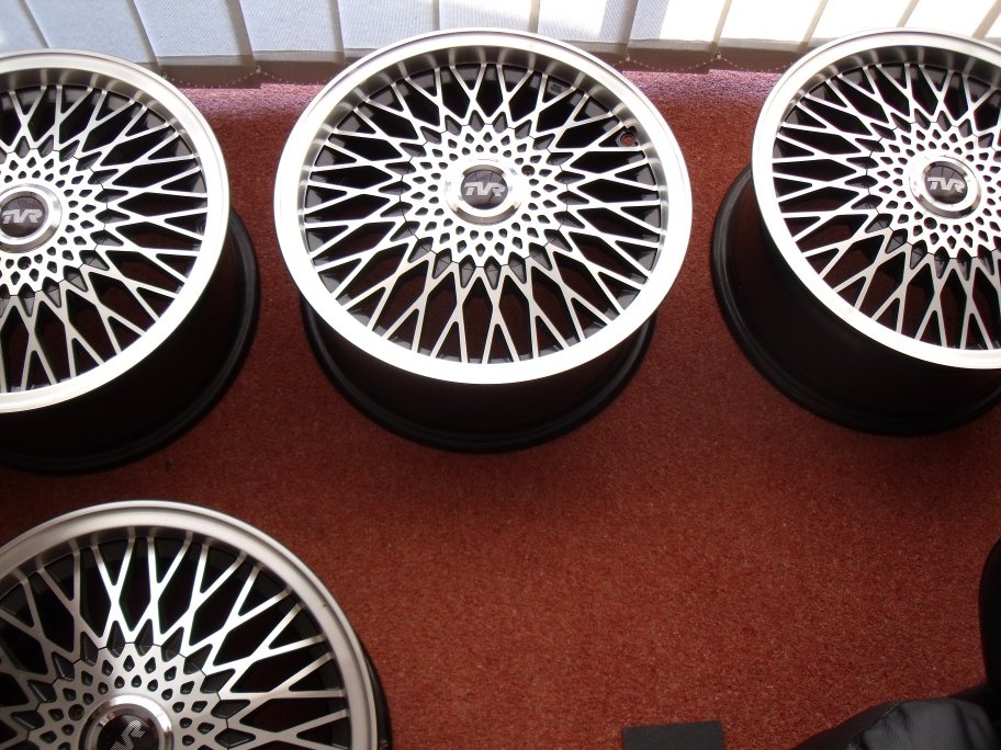
Just for information, the standard alloys on most Wedges prior to the 400SE were 7J x 15", with ET23 offset. The early cars ran 205/60-15 tyres; by 1987 it was typically 225/50-15. So now you know :O)
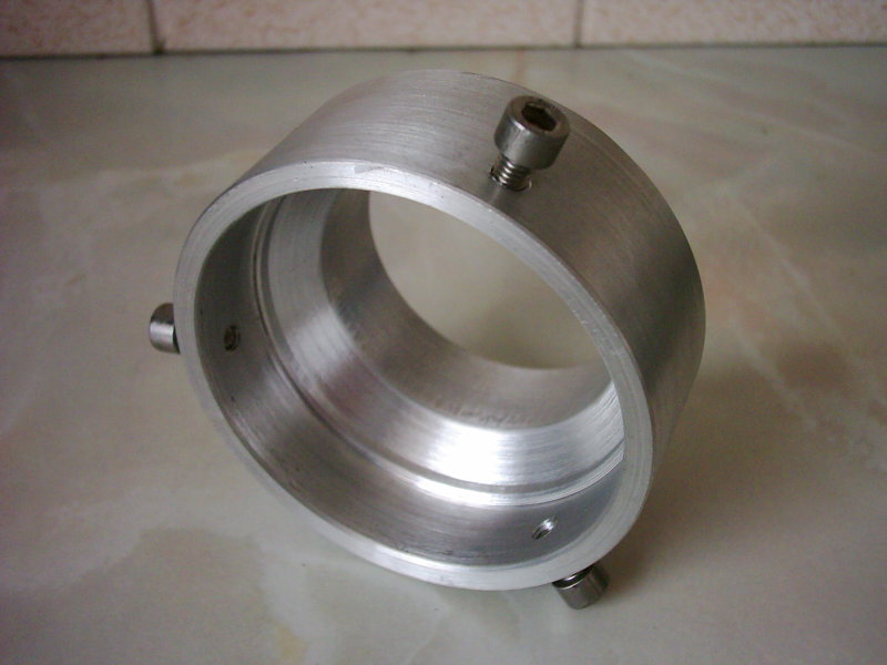
Hopefully less 'blingy', is the adapter I made to allow the standard flexible air hose to mate with the larger-bore Jaguar airflow meter that I fitted. Turned from 100mm diameter solid aluminium bar, it has a short internal taper to smoothly narrow the outlet of the AFM to match the hose:
Limited Slip Differential
The 390SE and some other models were fitted with the Salisbury HU LSD as used on the Jaguar Mk.X, E and (old) S-types, and possibly the XJS and some XJ6's as well... I came across this exploded view in an (I think) Autodata manual, so if you've ever wondered what the diff. looks like naked, here it is:
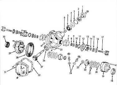
The parts labelled 20 and 21 are the friction clutches that allow the 'limited-slip' effect. Note that if you have to top-up (or refill) the diff, you must use LSD-specific oil and not standard SAE 80/90 gear oils. It takes 2.75 pints, the correct level is to the bottom of the 'Level' plug (not numbered but shown at far bottom left on the drawing). A common problem with these diffs is that the oil seal (2) springs a leak and dribbles oil all over the place. It can be changed with the diff still in the car - but beware! The driving flange securing nut was secured at the factory to a certain setting that crushes a collapsible spacer (6) inside the diff. If you under- or over-tighten on reassembly you risk premature wear and failure of the diff. The 'approved' method seen around the internet is to accurately mark the shaft, flange and nut and count the turns necessary to remove the nut. Change the seal then reassemble to exactly where everything was. Simple :O) If you want to see dirty pictures (of my differential!), look here