TVR Wedge chassis sill (‘outrigger’) repairs
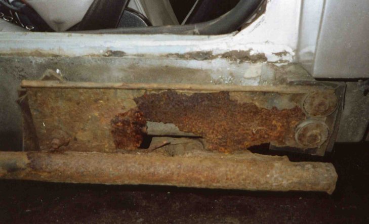
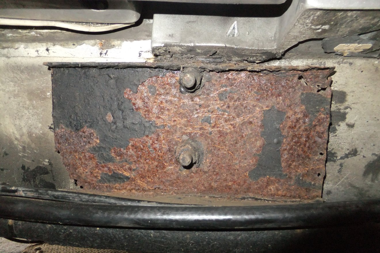
Typical corrosion (my 390SE, left rear plate; obviously terminal, as was the other side)
A common rot spot on the Wedges, and consequently probably THE most important part of the chassis to inspect when buying a Wedge, are the tubes and plates that make up the sill or outrigger sections of the chassis.
Between the early Series 1 Tasmins and the later Wedges, there were only minor changes in this area of the chassis. The more obvious modifications occurred in the engine bay, in order to allow fitment of the Rover V8 in place of the Ford V6. However, the dimensions of the tubes and plates do differ between the early and late cars: see the drawings for details.
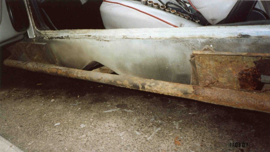
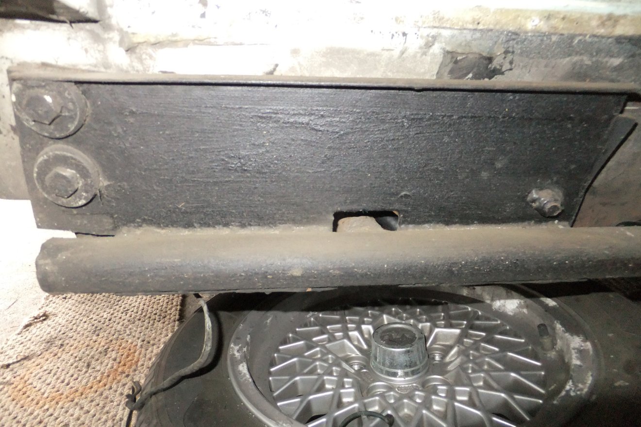
With the introduction of the 3.9L engine, the shortcomings of the original semi-trailing arm suspension were addressed by the adoption of the ‘A’ frame design; basically a single wishbone, with the upper link still being the driveshaft. A 'torque reaction' rod (or tie-rod) was incorporated, that links the ‘A’ frame to the rearmost chassis tube under the seats. To allow room for the tie-rod, this rear chassis tube was moved forward a few inches. The result was a cutout in the sill plate that did not appear on the pre-‘A’ frame cars.
NOTE: With the introduction of the 'SEAC' cars, major changes occurred to the sill area of the chassis that were eventually extended across most of the model range: the bodyshell lost some of the detachable sections including the sills, which makes access to the outrigger tubes difficult. In many cases a 'body-off' approach is necessary although a few enterprising folk have devised ways of fabricating chassis sections that replace all the tubing from the spine of the car outwards; this is however outside the scope of this article and if you have a corroded late chassis you may have to seek advice elsewhere.The quick way to identify the modified chassis is to check whether the sill rails are square, rather than round section. As far as I know, all 400SE cars as well as late ('US-spec') 280i's got the modified chassis whereas the 350i and 390SE seem to have continued for the most part with the original design.
The chassis tubing is 1.5” (38mm) outside diameter mild steel with a 14 swg (2mm) wall thickness. The sill plates, which provide various mounting points and reinforcements, are also 2mm mild steel.
Effective repair of these areas is not difficult providing you have access to a reasonably equipped toolkit, a large vice, an angle grinder and a MIG welder. The MIG doesn’t have to be huge: 120 Amps is adequate (I have an Oxford but SIP, Clarke and others make serviceable equipment). The required pieces are simple to fabricate as long as you have a hefty bench vice, a big hammer and a drill. The actual materials cost used to be surprisingly low (I’ve replaced both tubes and all four plates and had change from £23) but the cost of steel has gone up a lot in recent years: the job is however very labour-intensive and hence it costs to have the work done professionally.
Briefly, the sill tubes are welded across the protruding ends of three outriggers that pass under the floor from the central ‘spine’ of the chassis. The forward outrigger is actually formed by two tubes, is thus fairly rigid and acts as a good datum point for measurements.
To the sill tube are welded two sill plates: the forward one supports the bottom end of the door ‘A’ pillar tube (inside the car). The door hinge is bolted through the bodyshell to this tube, so if the lower end lacks support due to corrosion in the sill, the door hinge can flex the shell and crack the glassfibre. There may also be some reduction in the efficiency of the side-impact protection.
The rear sill plate carries one of the seatbelt mountings and the lower end of the door ‘B’ pillar tube; this tube runs up inside the bodyshell and carries the door striker plate, the seatbelt reel and top pivot, and on the Fixed Head cars, carries on up to the roof. On the Drop Head cars, the ‘B’ pillar carries the hood hoop pivots (and ultimately the roof!).
So it is obvious that any weakening of the sill steelwork is A Bad Thing. What can be done about it?
Perhaps the easiest way to outline the job is to begin at the beginning, assuming that your car has failed the MOT due to an unspecified amount of corrosion in the sill area of the chassis.
First you need to gain access to the sill. This is where, as outlined above, owners of SEAC, 400SE and later big Wedges will have a problem, as the sill covers were made non-detachable (there’s a moulded ‘join line’ below the doors, but it’s only for show!). You may find that a 'body-off' restoration of the chassis is called for; some specialists offer this service but equally, several owners have performed the work satisfactorily in a DIY setting.
Assuming that you have removable sill covers then: depending on what the guys on the production line had to hand, you will find an assortment of methods of mounting the covers. There are commonly two large dollops of mastic between the sill cover and bodyshell, somewhere in front of the door, and just behind it.
The easiest way to find the mastic is to insert a slim blade such as a stiff wallpaper scraper into the gap between sill cover and bodyshell, and move the blade forwards and backwards. The mastic can usually be sliced through by judicious application of the scraper. Note that the mastic often hides bolts or screws!
There are sometimes a few self-tapping screws that are inserted from inside the car, down in the footwells. Later cars used captive studs glassed into the sill covers, with nuts accessible from inside the footwells (under the carpet!), and behind the seats, just below the seatbelt reel (remove cabin trim). In all cases there are usually a handful of pop rivets along the top flange of the sill cover, just below the door seal, and a few more underneath the car. Sometimes the sill cover is rivetted directly to the floor; in some cases there are alloy brackets supporting the lower edge of the sill covers. Whatever you find will have to be overcome in order to remove the covers! If you have to get destructive, then it’s usually a simple matter to reinstate cracked GRP and replace captive studs with stainless ones, so they don’t corrode again….
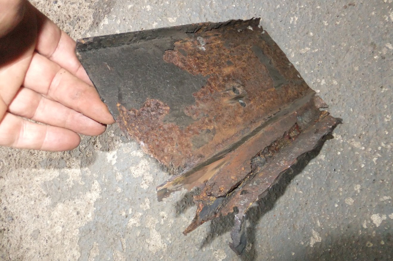
Once the covers are off, it will rapidly become obvious how bad things have become! In worst cases, the chassis rail will have large holes or even sections missing: the sill plates may be perforated or have been eaten away from the edges. In this respect, it’s usually the rear sill plates that suffer most. For this description we will assume that both the tubing and the plates are beyond saving… it’s unlikely that the tubes would be worse than the plates, though it’s possible to replace just the plates as long as the tubes aren’t too bad. I find that if a grinding disc in a drill can take the tubes back to shiny steel without producing any holes, they’re probably OK. It’s generally accepted, by the way, that DIY repairs in this area are fine as long as you don’t allow the chassis to twist whilst the sills are chopped up. In practise this means keeping the car straight and level while you do the job. Not too difficult; I’ve done the job in the street by just running the wheels up onto the kerb to allow more room underneath for swinging the MIG torch.
Lots of flaky paint...
So, where to start. You can identify the seatbelt mounting (the nut welded to the rear plate, which can be ground off and re-used if you’re careful) and the A/B pillar tube mountings: any remaining bolts just help to keep the bodyshell in place. Remove all nuts and bolts. You may as well grind them off if they’re rusty, and fit new ones. Recover all rubber bushes and packing pieces, noting where they went.
Before cutting anything, check as far as possible that your car has the dimensions shown on the drawings. Note down any apparent differences, but be aware that some tolerance exists by virtue of the holes in the bodyshell being rather larger than the bolts anyway.
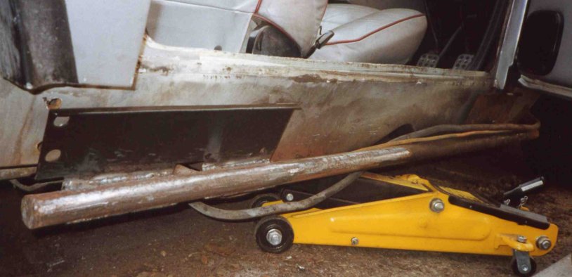
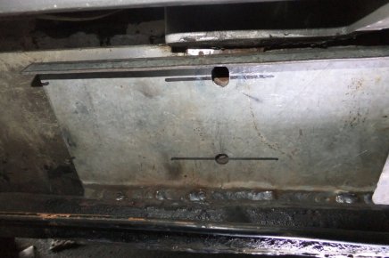
Now for the good bit: apply angle grinder and chop the sill tubes out. Don’t get too close to the outrigger tubes at this stage: you can clean up these areas once the bulk of the rot is out of the way. You should then aim to recreate the 'fish-mouth' shape of the tube ends to allow a good fit against the new sill tube. I usually start by cutting the new sill tube to the required length and offer it up frequently, cutting the front end of the tube to match the end angle of the front outrigger last. Now you can weld the sill tube in place, taking precautions against fire, weld spatter on paintwork etc. Some dexterity is needed to weld right round the outrigger tubes, but be aware that current MOT regulations stipulate that all chassis welding must be continuous - you can't 'weld a bit, miss a bit' as in the old days! Make a blanking plate for the rearmost end of the tube on ‘A’ frame cars (as next picture).
Fabricate the new sill plates as per the drawings, then offer them up to the sill tubes and secure parallel to the bodyshell with a ‘G’clamp, checking alignment of all holes before tacking in place. Make any adjustments with file, drill or grinder, then complete the welds. The plates are welded along their lower edge, and in the top ‘valley’ formed by the plate and tube. (If you are just replacing the plates, it’s possible to carefully grind out these welds and remove the old plates).
(New right rear sill plate on my car; note tube actually solid once surface rust removed)
Now you want to ensure that rust stays away for a while: apply suitable paint and underseal in liberal quantities.
By now you should have discovered whether or not the mountings at the bases of the ‘A’ and ‘B’ pillar tubes require replacing: generally if the sill plates are well rotten, the rust will have travelled across to the pillars and done its work here as well. Unfortunately, access is tight to say the least inside the car, so removal of the tubes ( a major task!) is probably the only way to do a proper job. Again, 2mm plate should provide adequate reinforcement here.
Once everything is structurally sound, refit rubber spacers, bushes etc. and reinstall all bolts. Ensure that seatbelt is refitted correctly.
Refit the sill cover using whatever means provides a secure mounting (not necessarily how the factory did it!).
I skipped quickly over the actual fabrication of the sill plates because there are various methods for achieving the folded edges and so on: I resort to a big hammer, a big vice and some 2” angle iron to clamp the plates while I whack them into shape. A heavy-duty sheet metal folder would make short work of them, I’m sure…
The exact dimensions aren’t too critical: basically you need enough metal once the edges are folded to allow drilling of the various holes. I usually fold the edges, work out how far out from the drawings the resultant plates are, and correct the hole centres accordingly. Owners of the earlier cars have an easier task, as only one edge of the plates needs to be folded.
An AutoCAD drawing showing the chassis dimensions will be available shortly.... and note that there are at least three variations on the theme, so you'll have to check your car to see which version you have!
Back in 2005, Tony Mather brought me his 1983 280i FHC when he found that the sill tubes were rotten. The chassis is one of the grey epoxy-coated ones; this coating is very thick (around 1mm in places) but still gets chipped and cracked, allowing moisture in.
I thought this would be a good time to create a photo sequence of the whole job, so I've created another page here if you want to see Wedge carnage... :-D
During some extensive work on my 390SE in 2013 I discovered that the front offside sill plate was corroding away...
There seemed to be little point in postponing the job so the sill cover was removed (quite easily, helped by the stainless steel screws I used 12 years earlier!) and the angle grinder brought to bear...
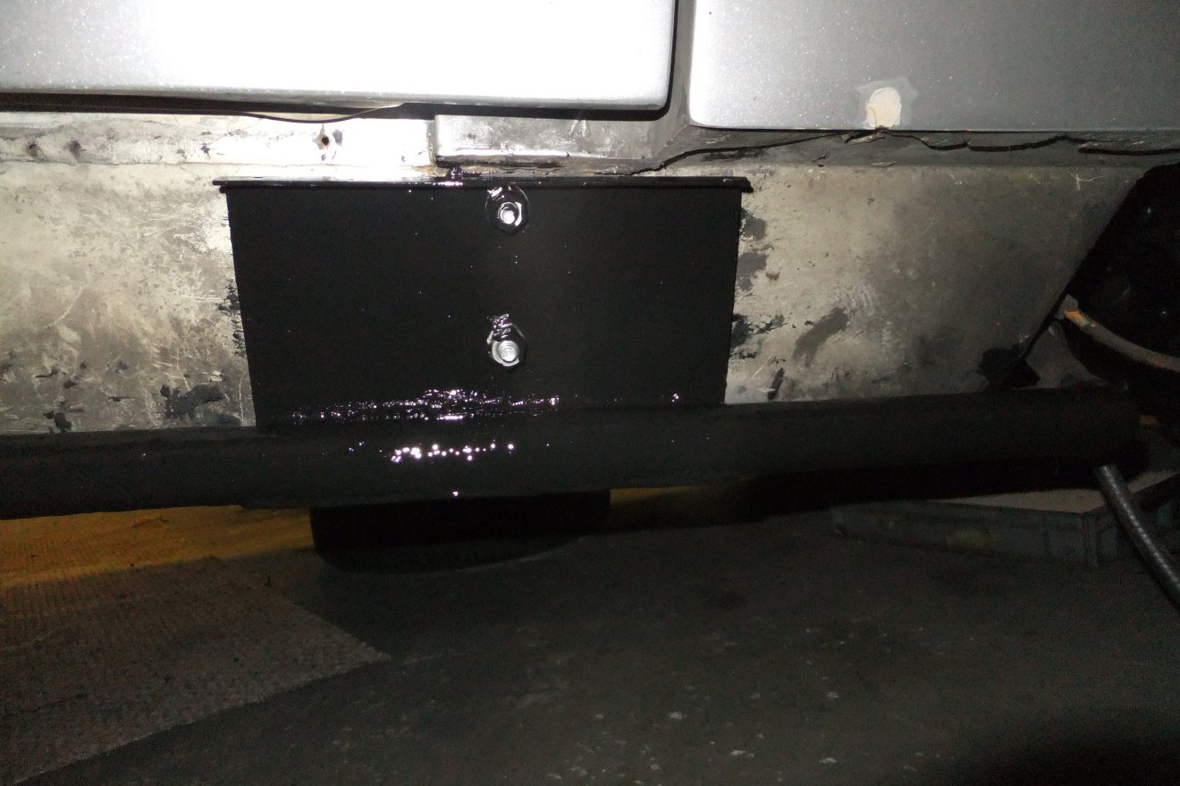
As an aside, here's the rear plate on the same side, the one shown further up the page that was replaced in 2001:
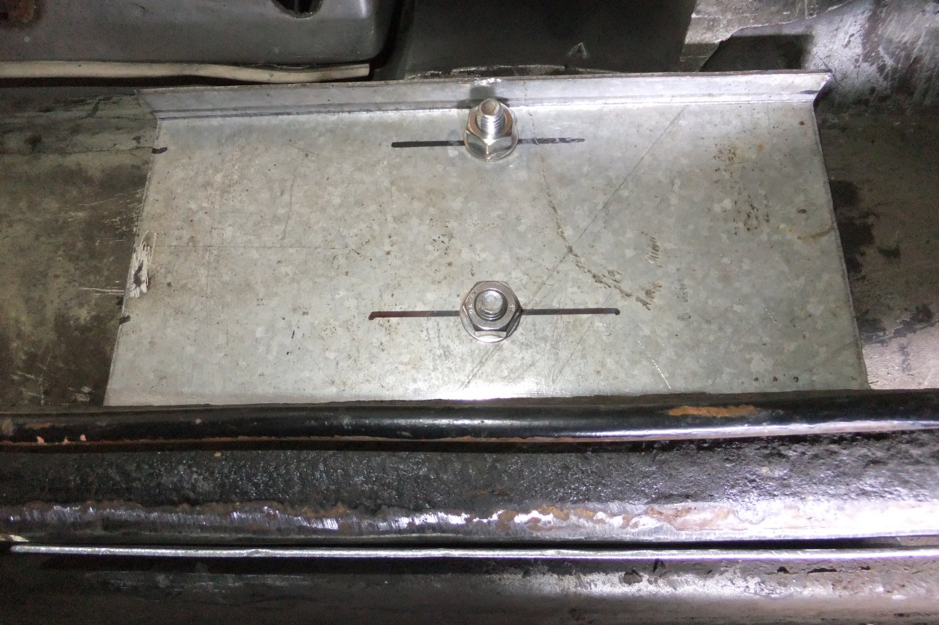
As you'd expect, a good coat of paint and some underseal is keeping the dreaded tinworm at bay. Anyway, I measured up, marked and cut out some of the galvanised plate...
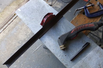
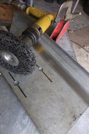
... which was duly folded (vice and a big hammer again!) and the bolt holes drilled. Then I used an abrasive disc to remove the galvanised coating in the areas to be welded:
The plate was offered-up and clamped in place at the correct angle ready for welding...
... and the welds completed.
A coat of paint and, once that was dry a coat of underseal and with any luck it'll be another 26 years before anyone needs to repeat the job :) I guess I should check the nearside front plate now, of course...