Front Suspension and Steering
If you're familiar with the TVR wedges you'll know where the various components were originally used but just to recap for those who may have just bought a Wedge and are splitting their time between searching the internet for clues and banging their head against a wall, here's an outline of what you're looking at (or for)... and it can be summed up in two words: Cortina and Granada. Hang on, you cry, what the hell is a supposed sports car doing running around on the pressed tinware of the Dagenham Dustbin? Well panic not; even the hallowed Lotus Esprit cheated and nicked it's bouncing bits from the lowly Triumph Herald, and you never hear a bad word about the handling of an Esprit...
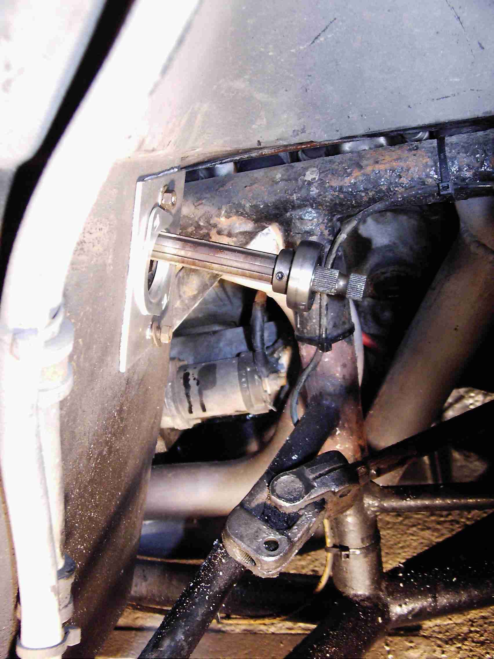
Think about it. The geometry of front suspension is complicated. All that camber, castor, Ackermann angles, self-centring, true rolling, toe-out on turn... lots of other car builders have used entire front beams from the Cortina et al to simplify their own calculations (my dad and I built a Merlin TF kit in 1982 and that used the Cortina beam, wishbones, hubs, rack, column... engine, gearbox, back axle and propshaft!); in the case of the TVR the track is different so the beam itself couldn't be used but the Wedge chassis incorporates a fabricated facsimile to get the ex-Cortina suspension arms in the right place. The factory used the non-PAS rack on the early cars, then later the PAS rack from the V6 Cortina was fitted, with the Ford pump being mounted on all sorts of bracketry which sometimes resulted in it facing backwards in the engine bay! By the time the V8 came along the optional PAS used the V6 Cortina rack, powered by the pump from the SD1... but even then the pump can be found in different places depending on whether the car is RHD or LHD, whether aircon is fitted, whether the fitter had been in luck with the missus last night etc. etc. Later models used a Supra Engineering rack (NOT the rack from a Toyota Supra as some people misunderstand it). As far as my 390SE is concerned it's the ex-V6 Cortina rack (actually made by Cam-Gears for Ford and it resembles no other Ford rack) with the SD1 pump hung off the front of the left-hand cylinder head... like this:
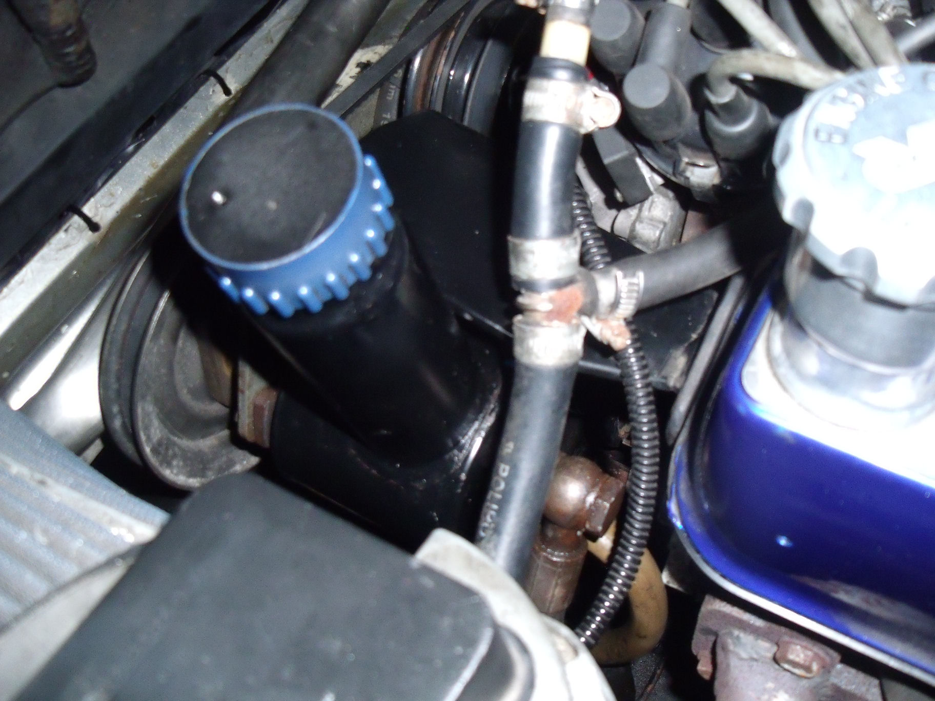
The big black bracket it hangs off seems to be a Blackpool-bastardised thing that bolts to the front of the left-hand cylinder head; it would be nice if it was all square but it's not. As you can see in the next picture (from the other side of the engine bay), the pump is slightly askew leading to the pulleys being out of line:
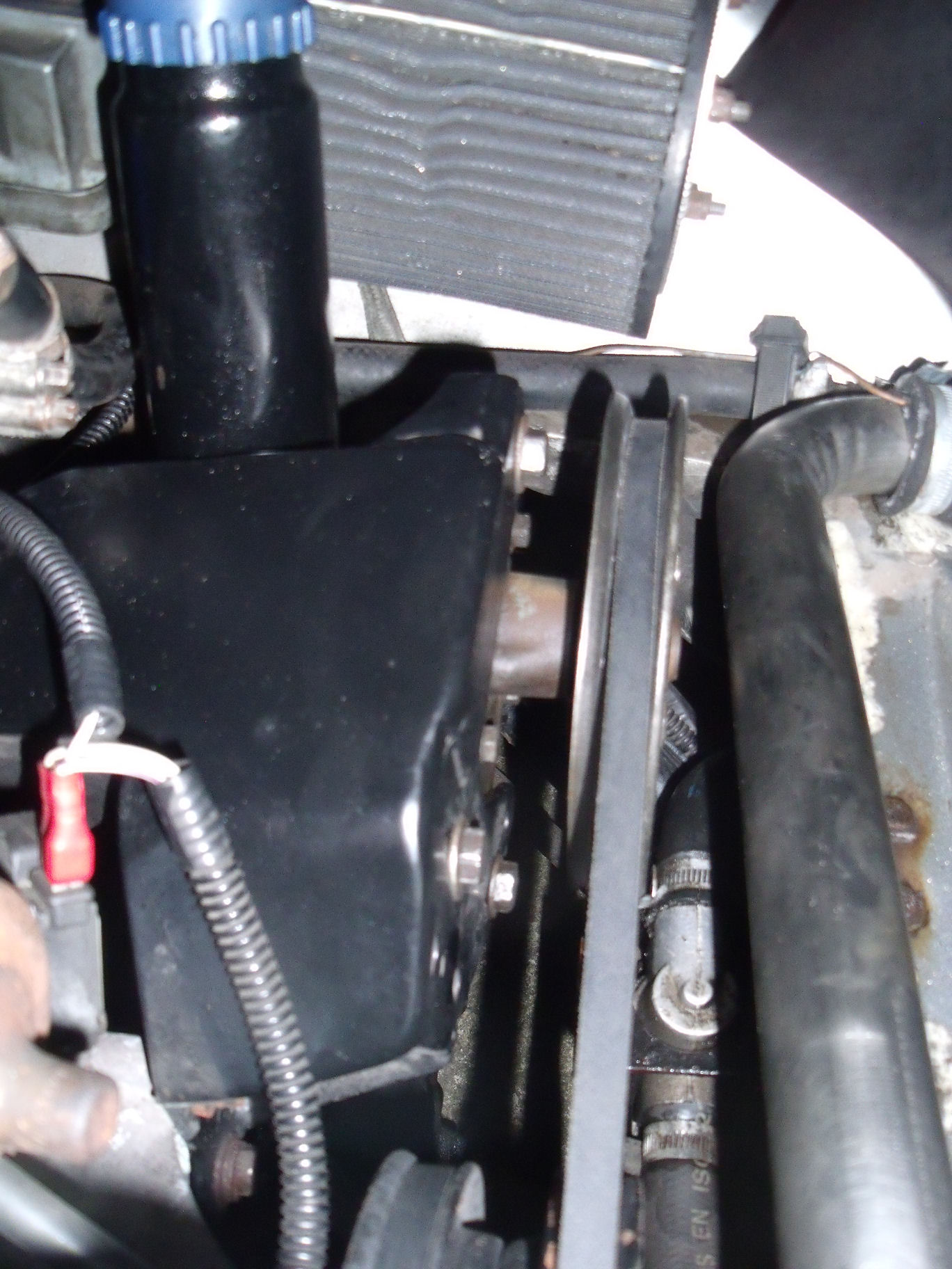
...but it has evidently been like that for the last 31 years so it must be OK ;O) .
As said, the Wedge track is wider than that of the Cortina so TVR had the racks modified with longer track rods (perhaps, but not confirmed as, those from the Granada). So care is needed if you go looking for a replacement. Still awake? Good. Next up are the hubs: the Cortina had 4-stud hubs where the Granada had 5-stud and that's what TVR used - Granada hubs, bearings and carriers (uprights). The track rod ends are the same thread for either and the balljoints are Cortina (the Granada ones look the same at a glance but are longer so if you try to fit them, the holes don't line up). Springs obviously are specials for the car; the anti-roll bar may or may not be, I've never found out.
The early cars suffered from a design miscalculation: perhaps to avoid criticism of the whole suspension being ripped-off the Cortina, the TVR chassis guy re-positioned the tie bars to point backwards (in compression) rather than forwards (in tension) as on the Ford; perhaps the intention was to reduce the amount of structural metalwork at the front of the car. This meant that the early cars suffered (and still do, those that survive) from rather bad bump-steer. In the 'Series 2' redesign the tie-rods were quietly moved back to where they should have been so that was one problem addressed, however the Wedges continue to have a reputation for 'lively' steering. PAS is definitely worth having as, although on the move the car is responsive enough, around town and when parking it does help if you have shoulders like Arnie to muscle the thing about!
TVR, in their infinite wisdom, decided to use the Rover SD1's rubber bush to support the lower end of the steering column, where it passes through the footwell into the wheelarch. Needless to say, this gets all the crap that the tyre sprays up and then wears, allowing the column to move around and generally detracting from the whole steering experience. The offending item looks like this:
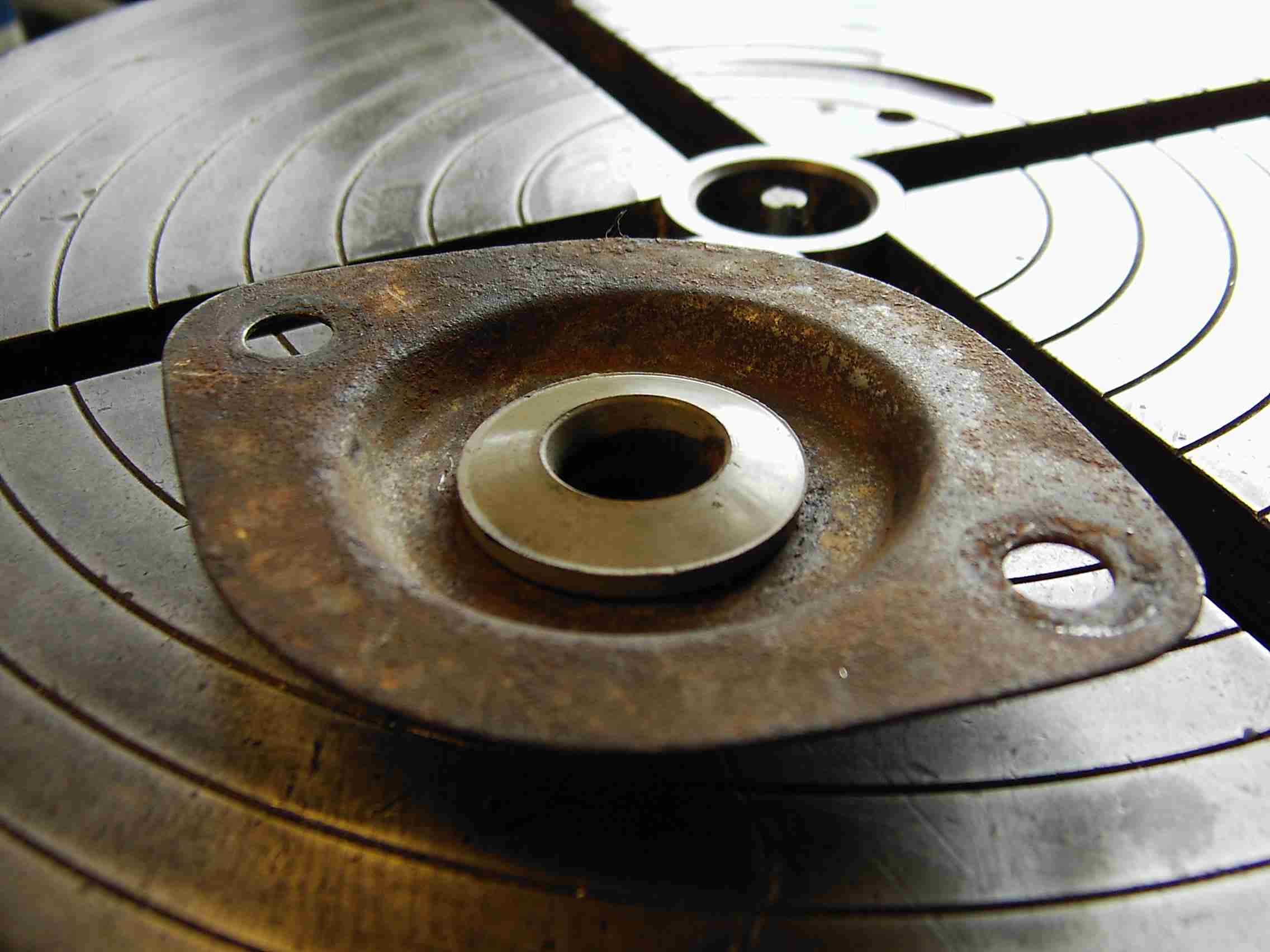
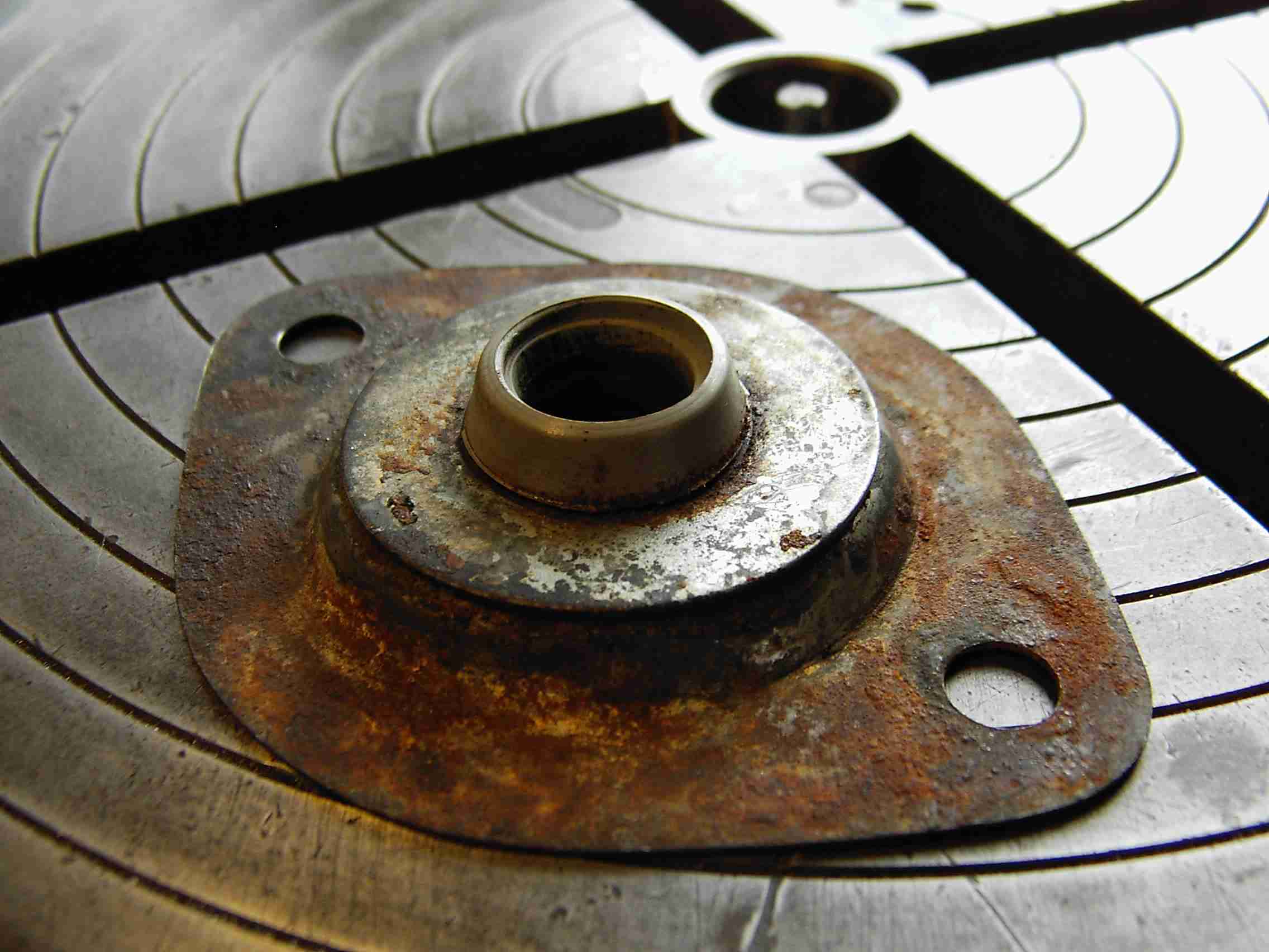
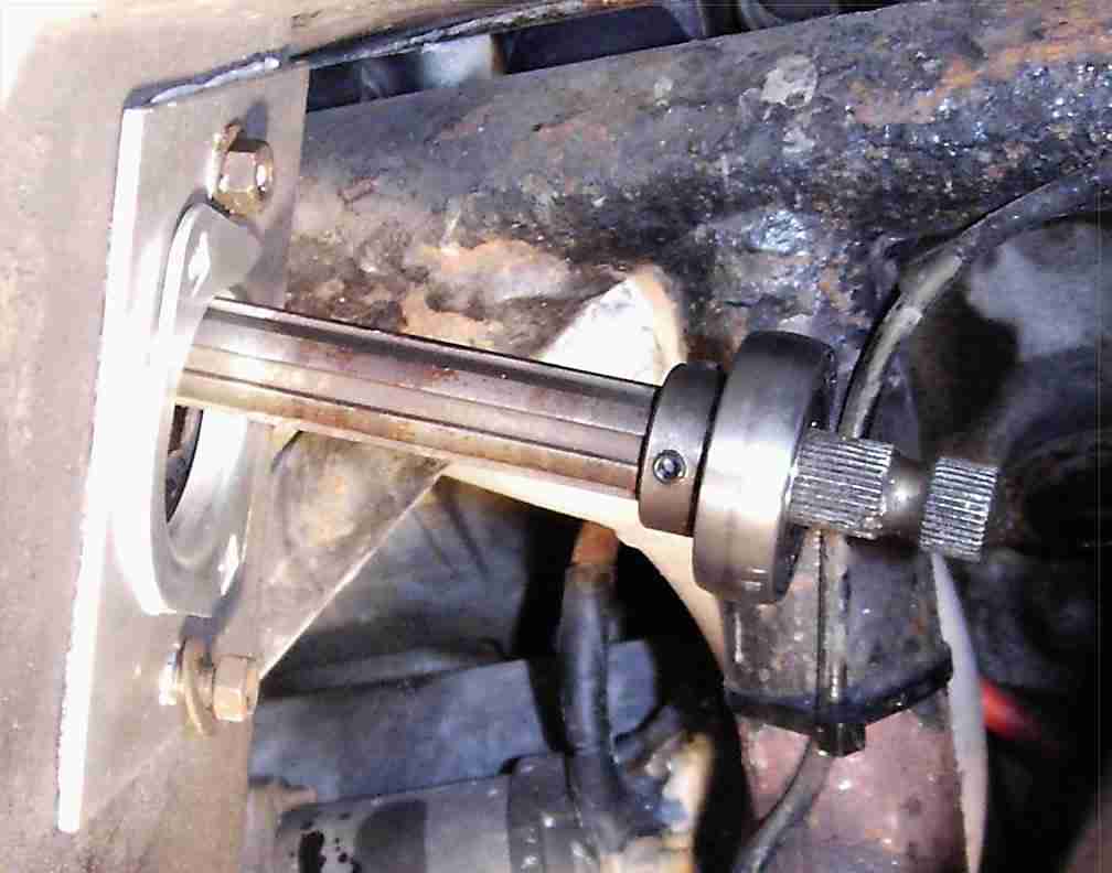
Some time back, one of the internet's 'Wedge' crowd devised a modification using a sealed ball bearing held by two elliptical plates. These are often used in industrial machinery to support long shafts where they pass through sheet metalwork. The various steering columns used over the years had different diameters: I think the old TR7 column was half-inch, whereas the SD1 item as used on the 390SE is 14mm. Unfortunately, 14mm is not a standard ball bearing bore size. I purchased a 17mm item and turned down a brass sleeve on the lathe. The sleeve is a snug fit around the column and the bearing has two grubscrews to lock it's inner race to the shaft, so with a drop of Loctite for good measure there's not much chance of the column moving around in the sleeve! Now it would probably have been a good idea to take photos as I was progressing... but I didn't, as the camera batteries were flat. By the time they'd charged up, I'd reached this stage:
The rectangular alloy plate is necessary because the elliptical plates of the new bearing are significantly smaller than the original bush's mounting plate, so not only would the bolt holes not line up but the hole cut in the GRP was so large that water would easily get past the new mounting plate. I cut a slab of alloy that is held by the original mounting bolts, and rotated the new bearing on it by a few degrees. It was the work of a few seconds to drill two more holes through the footwell, then the bearing was slid onto the column and all the bolts secured. I used silicon sealant between the footwell and each of the plates to provide water-resistance.
The old bush had only a small amount of wear, in fact it was mostly that the hole had 'ovalled' in one direction. I didn't expect a huge amount of improvement, but huge it certainly is. Previously, there was always a small amount of play evident if you shook the steering wheel. Whilst driving, the wheel would shake and shudder, almost as if the column universal joints were worn, which they weren't.
With the new bearing fitted there's no juddering, the steering wheel doesn't move and most remarkably, the actual 'feel' of the steering and what the front wheels are doing, has been transformed. I would honestly never have believed that it could be improved so much, in so simple a way, given how little wear I thought the old bush had.
In this close-up you can see the alloy mounting plate and one of the elliptical plates 'tacked' with grey silicon, with the new bearing in situ on the column. The bearing is a 'sealed-for-life' design with rubber seals either side of the balls.
UPDATE 2009
My car had been suffering for some time from an excess of bump-steer. As time went by I resigned myself to having to perform a complete suspension rebuild. Whilst I was enjoying myself on the bike in 2008 the car lay unused, although I had to pull it out of the garage from time to time to get my welding gear out. During one such event I found that the steering had suddenly become VERY heavy; it soon became apparent that the steering rack had leaked all the fluid into the drip tray below the car! I'd had a leak a few years earlier which was traced to an O-ring that seals the rack tube to the cast pinion housing. For some reason the leak had recurred. I jacked the car up to strip the rack and whilst I was under there I realised that the offside tyre was badly worn for about a third of its width to the inside. The other tyre was still fine, so something had to be amiss. Extensive prying with a crowbar showed that the offside lower suspension arm was able to move around on its mounting bush. Given the amount of PAS fluid about the place I presumed the fluid had rotted the rubber bush. Nothing for it then, the suspension would HAVE to come apart! For the time being I repaired the rack (again!), but a few weeks ago when I decided it was high time the TVR was back on the road I took a deep breath and got stuck in.
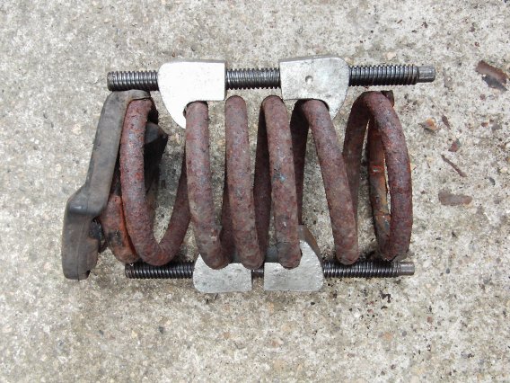
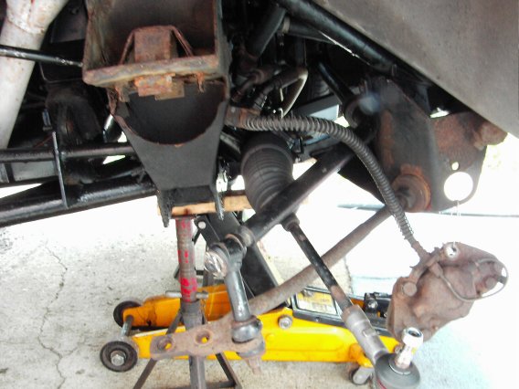
There's not much to it. Cortina suspension, that is! For the last few years I've been hearing tales that you can't use standard spring compressors on a TVR Wedge because there's no room, or they foul on the cylinder heads, or the rune stones are in the wrong alignment or whatever. Well, it's complete cobblers. Way back when I was a lad and my father used to regularly work on Cortinas, all he had was a pair of standard spring compressors. All these years later and all I have is... a pair of standard spring compressors. They went on, there was plenty of room, nothing fouled and the suspension was apart in no time. Just to prove it, look here:
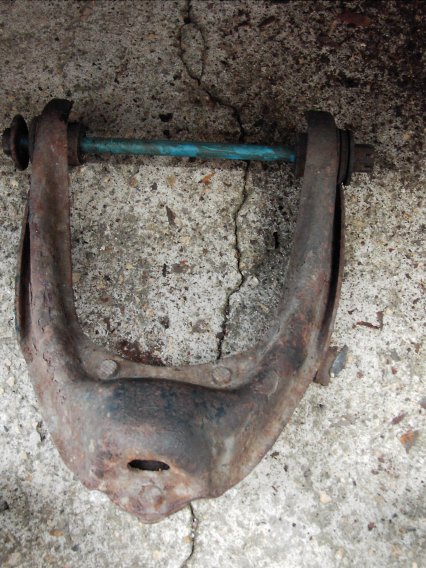
Granted, the rubber seat is wedged against the spring by the compressor thread. Not a problem. The lower arm bush, however, WAS a problem. I don't know about the PAS fluid eating the rubber but a blind man could tell you that this one is shagged:
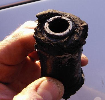
Yes, those cracks DO run right along the inner sleeve. No wonder the arm was moving. That bush and those fitted to the upper wishbone were Boge items; the replacements are some unbranded stuff, probably made in India from chewed-up elastic bands and llama droppings. Needless to say I didn't just bang the new bushes in and throw it back together (as would have happened when my old man did car repairs ;o) ... there was sandblasting to be done. Before:
...and after (yes, I did tape up the balljoint to avoid blasting it):
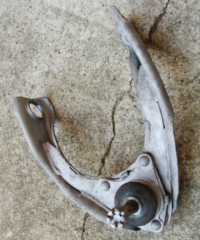
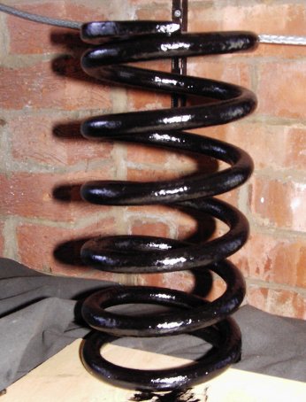
That upper balljoint is the original, factory-rivetted item and although I'd bought new ones, I honestly couldn't find any play in it that would suggest it was shot. So I left it (EDIT Oct 2018 - it's still there!). I painted the various parts before reassembly, including that spring, once I'd blasted 22 years of crud off it:
and the whole thing went back together almost as easily as it came apart, complete with new bolt through the lower arm pivot as the old one was worn from fretting against the cracked bush. There's the usual chassis rust too; here's a general view under the wheelarch with the suspension stripped off. I have new bushes for the tiebar; another job for another day...
Meanwhile the bump-steer has gone; the tracking alignment was reset when I had a new pair of tyres fitted so for the moment all is well.
UPDATE Oct 18:
After 18 years of listening to the power steering pump whining (sounded remarkably like a supercharger, shame it didn't add the same benefit!) I finally got round to doing something about it: I swapped it for a spare pump I was given not long after I bought the car. How that came about is thus: I'd been put in touch with an old guy who had a lathe for sale as I happened to be looking for my first machine tool. When I went to see the lathe I spotted a PAS pump on his bench and remarked that it looked like the one on my TVR. He said it was one taken from (if I remember it correctly) a BL/Rover Montego (remember them?!) he'd broken for spares; the only obvious difference was that the filler neck was shorter than the ex-SD1 unit on the TVR. When I went back to collect the lathe he put the pump in the van as a freebie. Being curious about the design (it's a Hobourn Eaton roller pump) I stripped it down, drew a little sketch, reassembled it and added it to the pile of bits that may come in useful one day - well, doesn't everyone? 8^/ When I dug it out nearly two decades later I soon realised that (a) it's quite badly dented, which I didn't recall and (b) whereas the SD1 unit has two hydraulic connections at the rear, the Montego unit has three - there's an extra threaded connection, smaller than the main high-pressure outlet. I assumed it's for a bypass, pressure relief or whatever but evidently it wouldn't be a straight swap as the ex-Cortina rack on the TVR only needs high-pressure feed and low-pressure return (and oddly, an internet search for info on the Montego rack suggests it too has only two connnections, so I wonder whether the extra threaded port was blanked off and I removed whatever was in there when I stripped it all those years ago..?). Then it occurred to me that the outer casing looks dimensionally the same on both, apart from the length of the filler neck. Would it be possible to swap the casings, leaving the extra hydraulic connection to do its own thing inside the fluid reservoir... what's the worst that could happen? So that's what I did. The casing is retained to the pump unit by the large threaded HP coupling on the back; with that undone the only thing keeping the casing in place is the friction of a large O-ring around the front (driven) end of the pump unit. Suitable prising and clouting with a rubber mallet got both the casings off and sure enough they're interchangeable. I used a smear of Wellseal on the O-ring just in case but the reassembled unit doesn't leak - and more importantly, it doesn't make any noise either! :D The odd thing is that the 'old' pump has no more outward signs of wear and tear than its replacement: the shaft bearings appear fine and there's just the sound of oily rollers when you spin it. That said, the swarf magnet fitted into a slot in the pump casting looked like a porcupine, there was that many metal particles stuck to it... so they've come either from the pump or the rack and on balance I'd prefer it to be the pump, those ex-Cortina PAS racks are a bit thin on the ground now!
In case you're not au fait with the design, this is the pump (ex-Montego version with the short neck shown):
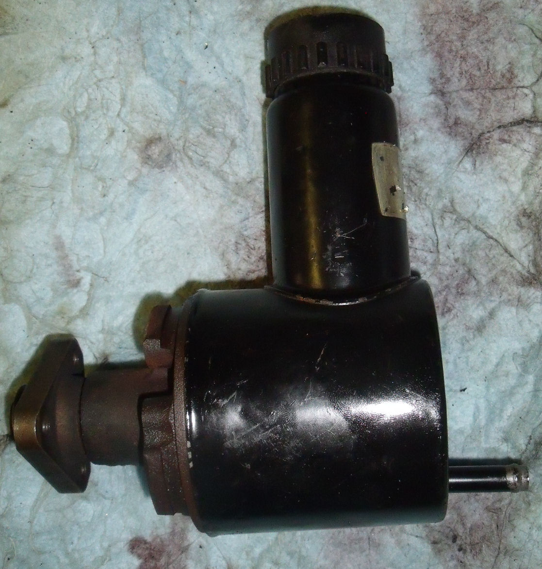
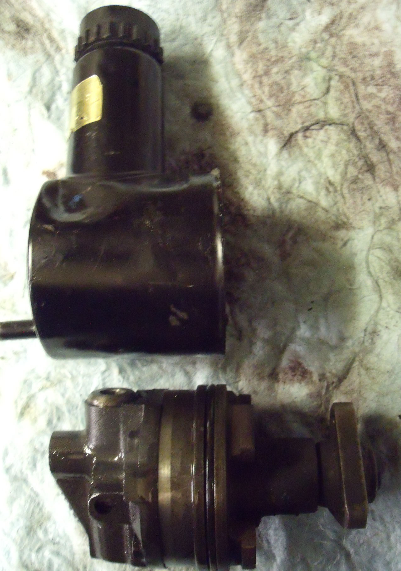
Here's the pump unit extracted from the (dented) outer housing which doubles as a fluid reservoir. Some versions of the Hobourn Eaton design such as those used on some Landrovers have a remote reservoir:
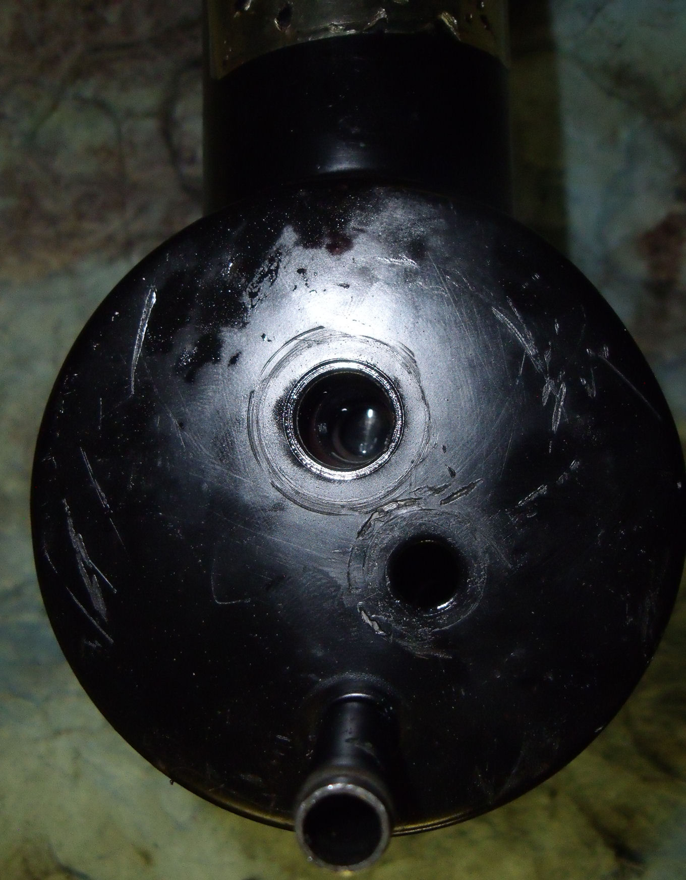
...and the rear view of the pump showing, in this case, the single HP outlet of the SD1 type and the swarf magnet vertically at left:
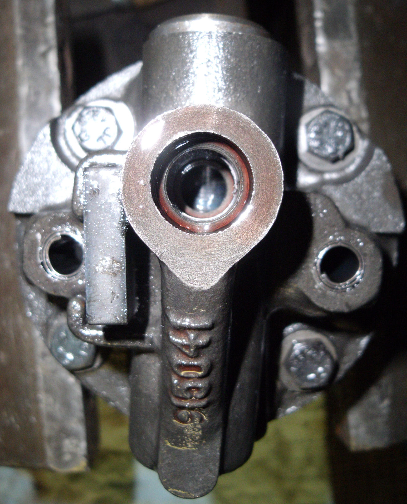
Rear view of the supposed Montego unit showing the ports for the two threaded couplings; the pipe stub at the botom is the LP return from the rack:
So although the lathe went the journey a dozen years or more ago and the old guy who sold me it could well be pushing up daisies by now, the freebie pump could (touch wood) run for a good while yet :)
In case you're interested, the principle of operation is that the rotor spins within a chamber which has a sort of elliptical profile - or perhaps a squashed figure-8. The rotor has a number of slots, each of which guides a hardened steel roller. The 'wide' ends of the ellipse are filled with oil from the fluid reservoir that surrounds the pump (the whole thing effectively runs permanently immersed in oil). As each roller approaches the narrow part of the ellipse it is forced into its slot in the rotor, compressing a small volume of oil ahead of it which is released to the pump outlet. As it proceeds to the other side of the ellipse, the chamber wall recedes, allowing the roller to be thrown outward whereupon the rotor slot refills with oil. The roller follows the chamber wall until it approaches the narrow part which squeezes it back into its slot... and so on. There's a pressure relief on the fluid outlet which lifts a piston against spring pressure to allow the pressurised oil back to the reservoir, unloading the pump. A portion of the high-pressure fluid is fed forward through the pump casting, filling the gap between the shaft and the plain bushing in similar fashion to the crank and camshaft bearings on an engine.
In case you're wondering, the answer's no. No, you can't rebuild these pumps! I thought I'd try to get to the bottom of why this one was whining, which if course meant a bench strip-down. I presumed that it was the shaft bearings that were kerry (from Kerry Packer, packered... knackered :D) and that all I'd have to do was pull the driving flange off, unbolt the back part of the pump from the front, drop the shaft out and change the bearings and seal. Er... no. First off, the flange doesn't pull off, press off, twist off or f-off: it's formed as part of the shaft which must therefore come out from the front. Second, although you can unbolt and remove the rear part of the pump, exposing the elliptical chamber, rotor and all the rollers, you can't get the rotor off the shaft. It looks like you should be able to: it's not a press-fit on the shaft and has a small amount of rotational play but is kept coupled to the shaft by a key. A key which you can't extract, because either side of the rotor is a spring wire circlip, and removal of the rotor clearly requires the rear circlip to be extracted, except you can't because the gap around the shaft isn't wide enough for the circlip to pass through even if you could find a way to spring the circlip open. Ah, thought I: I bet it's like a CV joint where the circlip keeps the two halves of the joint together until you give one side a good clout and the other half of the joint squeezes the circlip closed so it can pass over it. I bent my biggest club hammer trying (OK, not literally)... as well as bending my DIY press. Nothing gave way (except my patience). Then I had another look and figured that if I could spring the circlip in front of the rotor up onto the wider part of the shaft, the rotor would slide forward and leave enough room to extract the rear circlip. Yes, that must be it. Er, no. The rotor still wouldn't move far enough forward to let the rear circlip out. In the end I figured that the pump was as good as scrap anyway so 'in for a penny' and I clamped the entire assembly in the lathe and turned down the end of the shaft until the wire clip could pass over it. The rotor then pulled off, releasing the key which turns out to be a small roller. The second circlip was then sprung and the pump front body slid off the shaft. The next surprise was that there are no bearings - well OK, there are no BALL bearings. The shaft spins in a good old-fashioned plain bushing, with a high-pressure lubrication channel and return helical groove. There is a small oil seal at the outboard end and of course it wasn't leaking, but if it was it appears you can't replace the seal without destroying the pump so it's fair to say if the seal is weeping, you need a new pump! OK, 'destroy' is a bit extreme: I'd already worked out that if I could replace the hypothetical shaft bearings (and seal!) then I could rebuild the pump and weld up the end of the shaft to restore the piece that retains the circlip... but it still puzzles me how they assembled it in the first place, unless a lot of pressure was used to 'mushroom' the shaft end once all the parts were assembled on it. A good rummage around the internet has so far failed to turn up any clues as to how this design of pump may be serviced... so maybe I'm the first to realise they can't! I'm still puzzled as to why the swarf magnet was so 'clogged' (what is the term for a magnet covered in ferrous particles?!); although there are a few rough patches on the inner face of the pump chamber they are in the areas where the rollers would be 'off-load', and anyway the rollers themselves all look unblemished... which also begs the question: exactly what was making the pump whine? It wasn't due to a tight belt, I always leave a small amount of slack - the replacement pump has the same belt under the same tension and it is silent. Maybe it was the pressure relief valve letting-by, sort of a train whistle effect.
(Back) (Back to Wedges) (Back to Home)