Rear Suspension, Differential and Drivetrain
(Quick Update 260423 - I was recently contacted by Neil Russell of T&VR Services regarding the bushes I used in the rear suspension rebuild shown below. Neil tells me that they have the capability to manufacture new A-frames, inclusing a Rose-jointed version for race applications. Find them at www.tvrservices.co.uk)
2012 might have been a good year for some things, but driving my TVR wasn't one of them. I took the car for an MOT, taxed it and first time out, the bloody rear brakes overheated again!
I resigned myself to getting my hands dirty some more, but once I'd got the car jacked up and crawled back underneath I just had to admit I needed to spend some proper time (and money!) on the rear end gubbins. I'd had the car just shy of 12 years by this point and apart from one rear wheel bearing, diff oil and the brake issues, I'd pretty much neglected the drivetrain. There was diff oil everywhere due to seepage past the three seals (probably not helped by the brakes cooking), slight play in a couple of the UJs, the tie-rods were bent (although it never seemed to affect handling or tyre wear!) - and of course the brake problems.
I sent off for a road tax - sorry, Vehicle Excise Duty, a fine for daring to own a motor vehicle - refund, and wriggled into my overalls...
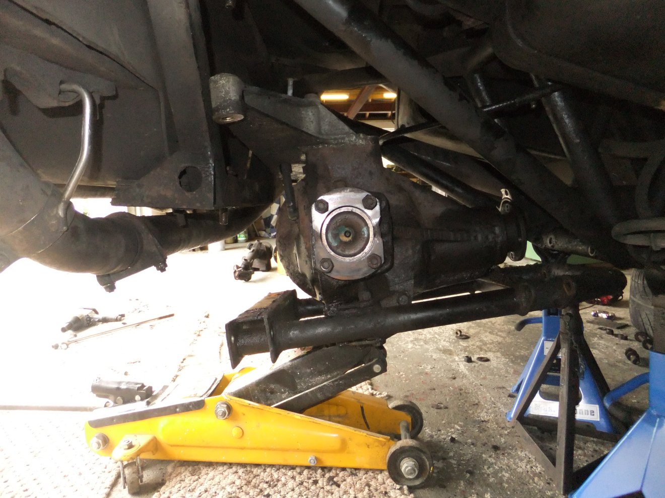
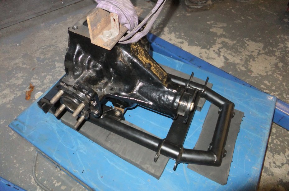
It was a fairly simple matter to disconnect and/or remove the springs, driveshafts, 'A'-frames (TVR's version of a wishbone), tie-rods, propshaft, calipers, discs, brake lines and handbrake cable. A couple of the diff subframe (or carrier) bolts were seized and I had to get destructive, but more on that later. Eventually I was able to lower the differential, complete with the upper carrier beam, out of the chassis:
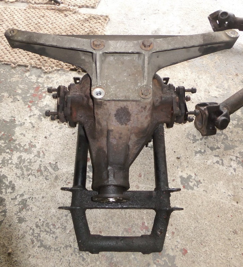
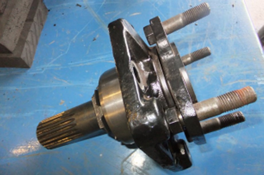
I should say here that the assembly is f- ff- fairly heavy ;o) - but eventually the diff was safely on the floor and I could get a good look at it:
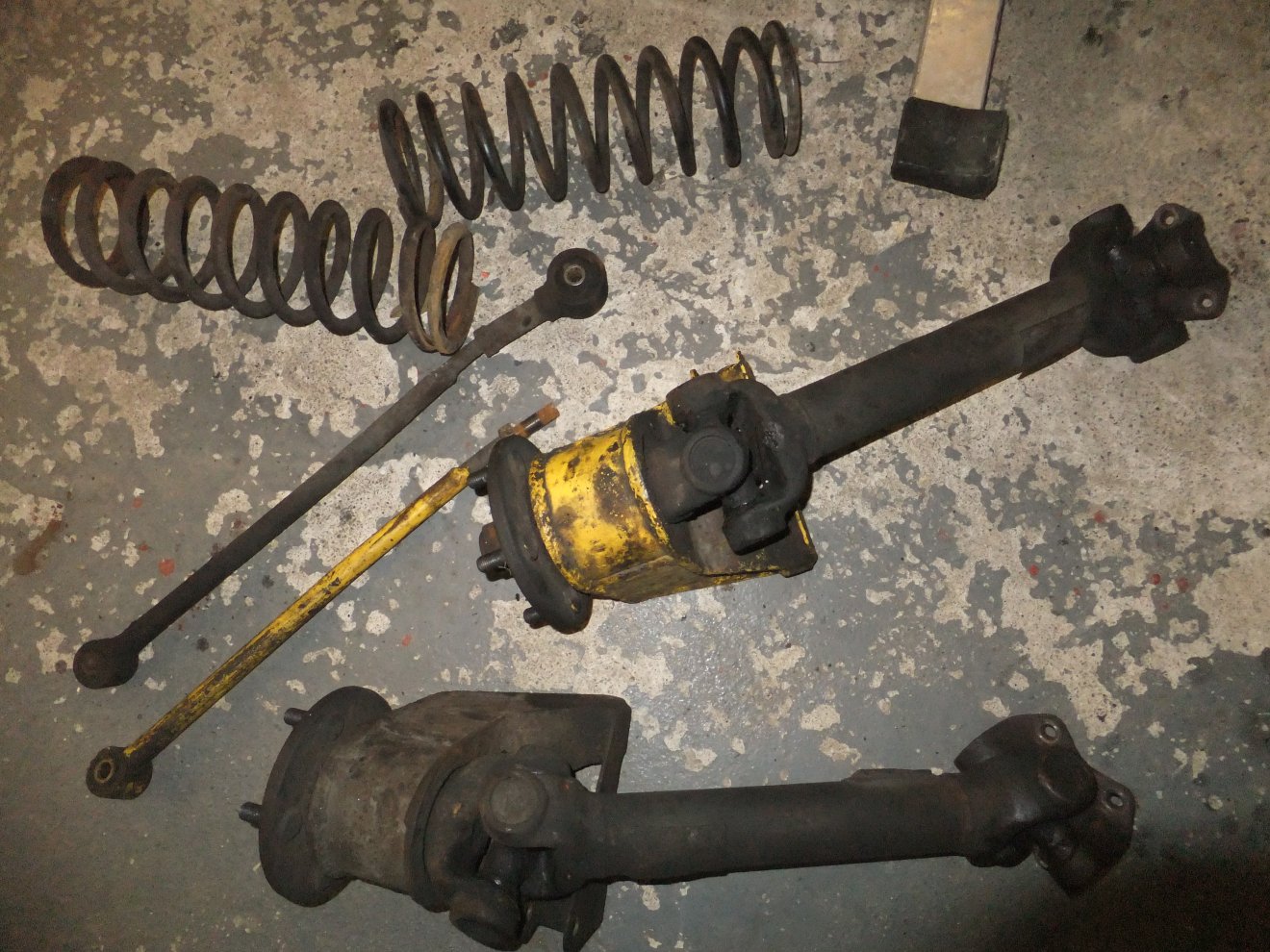
There was also a pile of other bits to trip over, but we'll get back to them later:
First I unbolted the alloy top carrier beam. On the early Tasmin the diff. was supported at the top by this beam and at the bottom by a simple tube cradle that locates it to the chassis. The mid-80's redesign (change to A-frames rather than trailing-arms) meant that the lower cradle was altered but the alloy top beam remained in use throughout Wedge production. They have been known to fracture around the end mountings but at first glance this one looks OK:
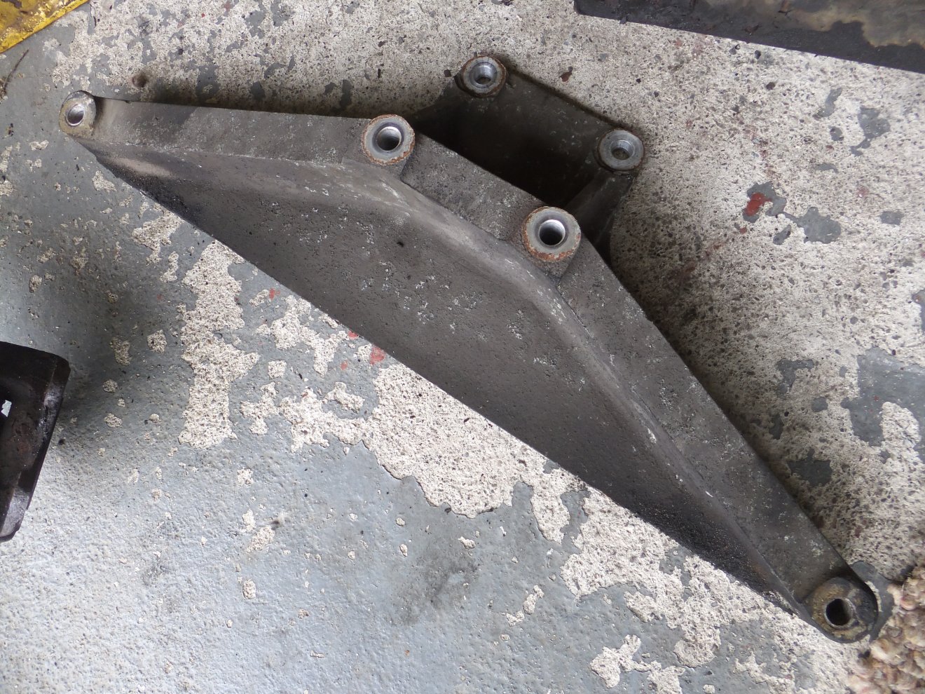
It was the work of a few minutes to sandblast 25 years of muck and oxidation off it:
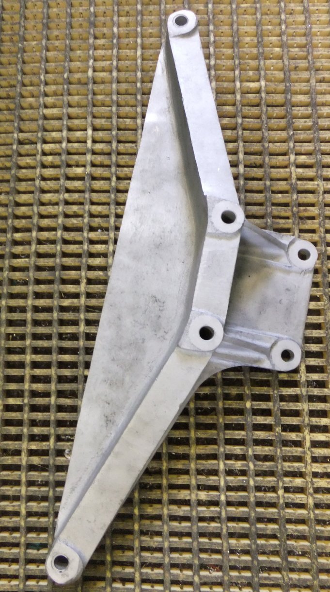
at which point a close examination proved the beam to be crack-free. Good start :)
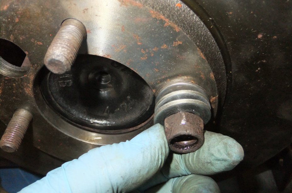
Most TVR Wedges were fitted with a standard Salisbury 4HU differential, as used in various Jaguar models until at least the early '90s. A Limited-Slip version was available as an option; later 'Big Wedges' mostly had the LSD fitted as standard equipment... the usual ratio for both types was 3.54:1 - which I'd always assumed was what my car had. Then I took a closer look at the tags fitted to the rear cover bolts. The one marked 'PL' indicates it's a 'PowrLok' (i.e. LSD)... it was the 3.31:1 that took me by surprise!
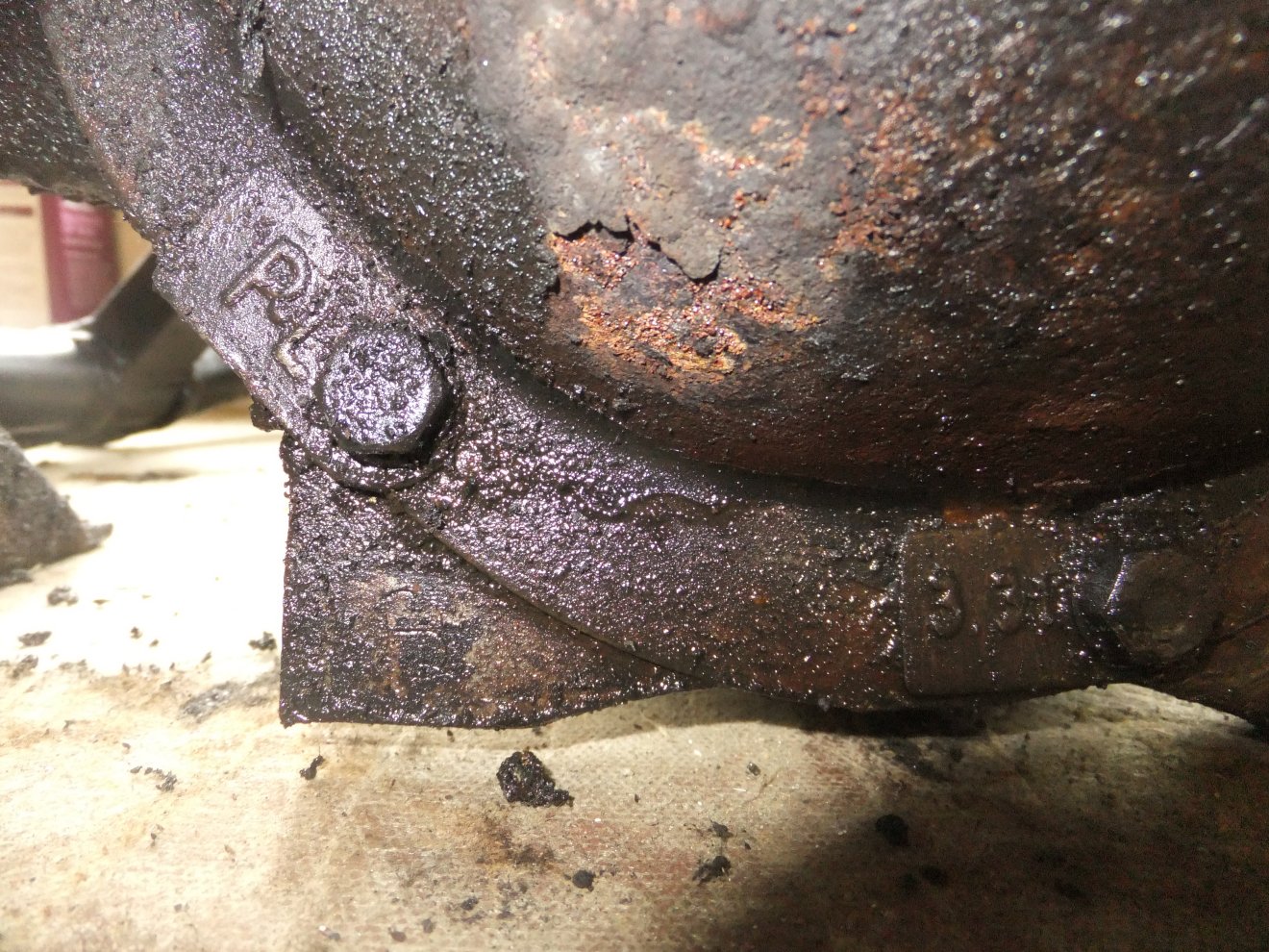
A quick check (rotating an output flange and counting how many times the input flange rotated) confirmed the ratio. Once the diff was dismounted from its lower cradle, I dunked the cradle in the parts washer to get rid of the accumulated clart. The bushes would be scheduled for replacement once the cradle was repainted or powdercoated.
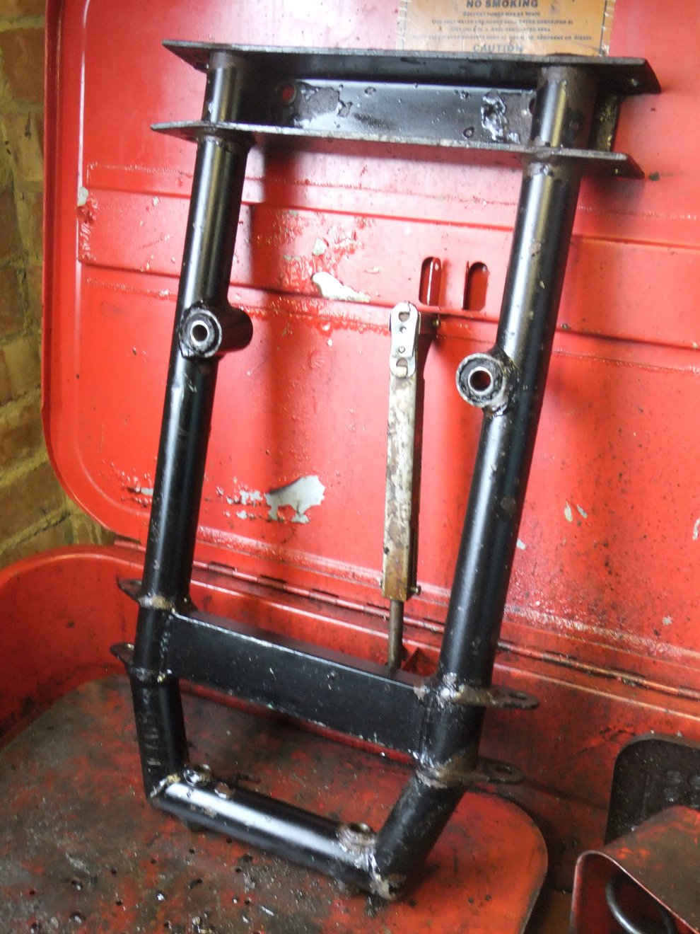
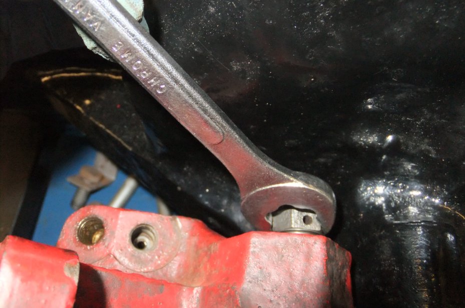
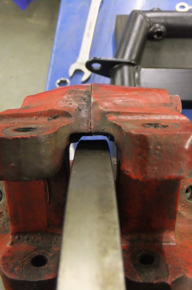
The slight splaying of the frame sides (top left of pic) is puzzling: that's one of the pivot points for the nearside A-frame (wishbone), I can only asssume that it's down to poor jack location or someone's had a lever in there to get the A-frame out at some stage. Either way it was a simple matter to bend the sides parallel again with a large adjustable spanner.
Back to the differential, then. I heaved it up onto a bench and propped it up on axle stands and wood blocks, in order to access the drain plug underneath:
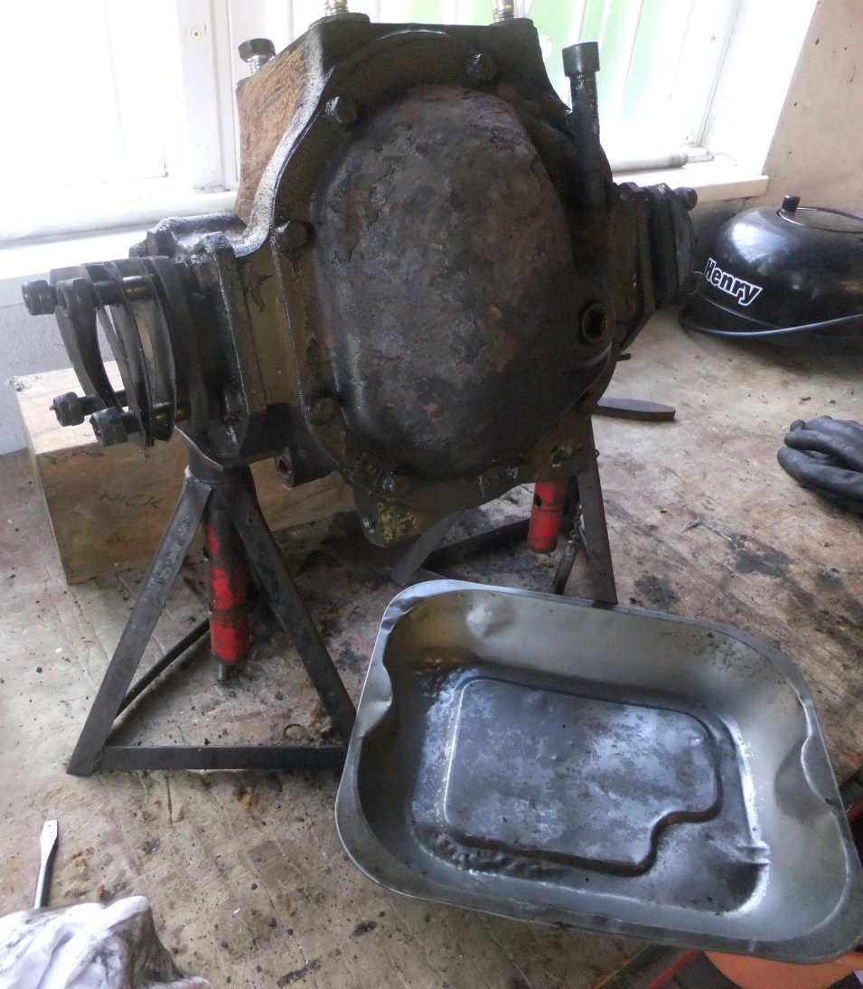
Unfortunately the drain plug had other ideas: it was so stiff that I was at risk of pulling the diff off the stands so I resorted to undoing the rear cover bolts and letting the oil drain that way. One advantage of removing the rear cover was that I could get a good look at the condition of the crown wheel:
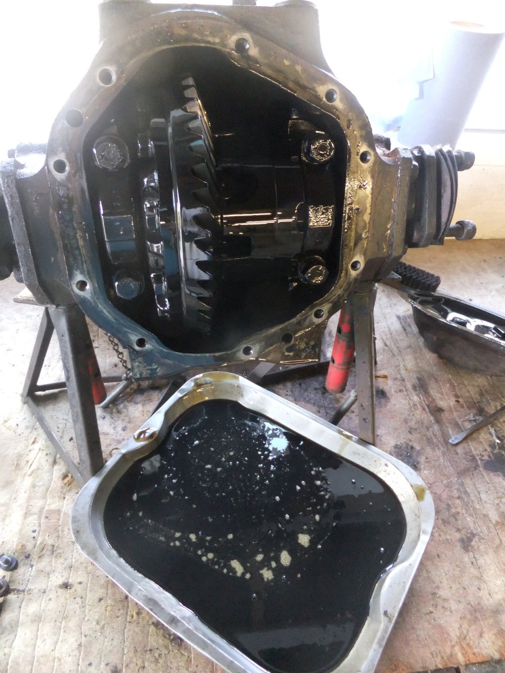
As usual with gear oil, this stuff stank to high heaven so I quickly decanted it into an old oil can ready for disposal (EDIT: six years later!). I reckon old gear oil would be the ideal anti-theft deterrent if you painted it on fences etc.!
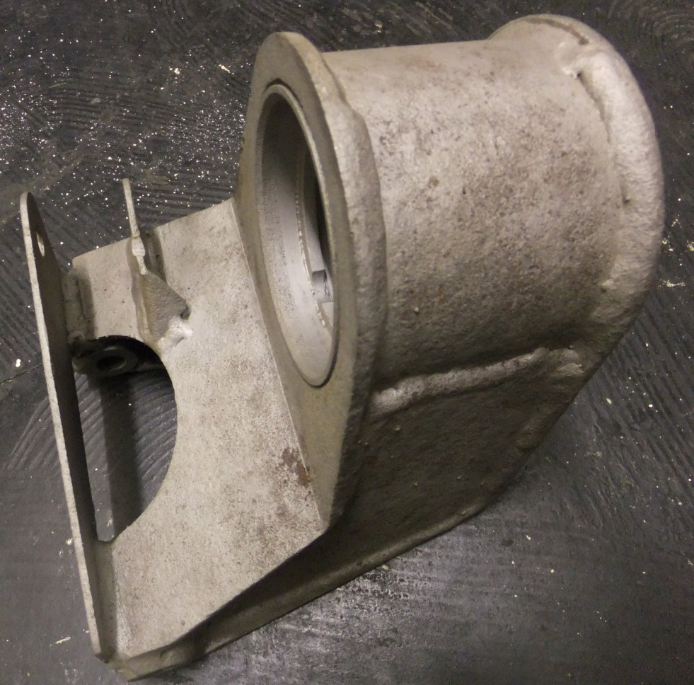
Next step was to undo the 5 bolts that retain the output shaft housings and slide the housings out. Access for sockets is a bit limited owing to the output flanges, perhaps a 3/8" drive set would have been a better choice but I managed it eventually:
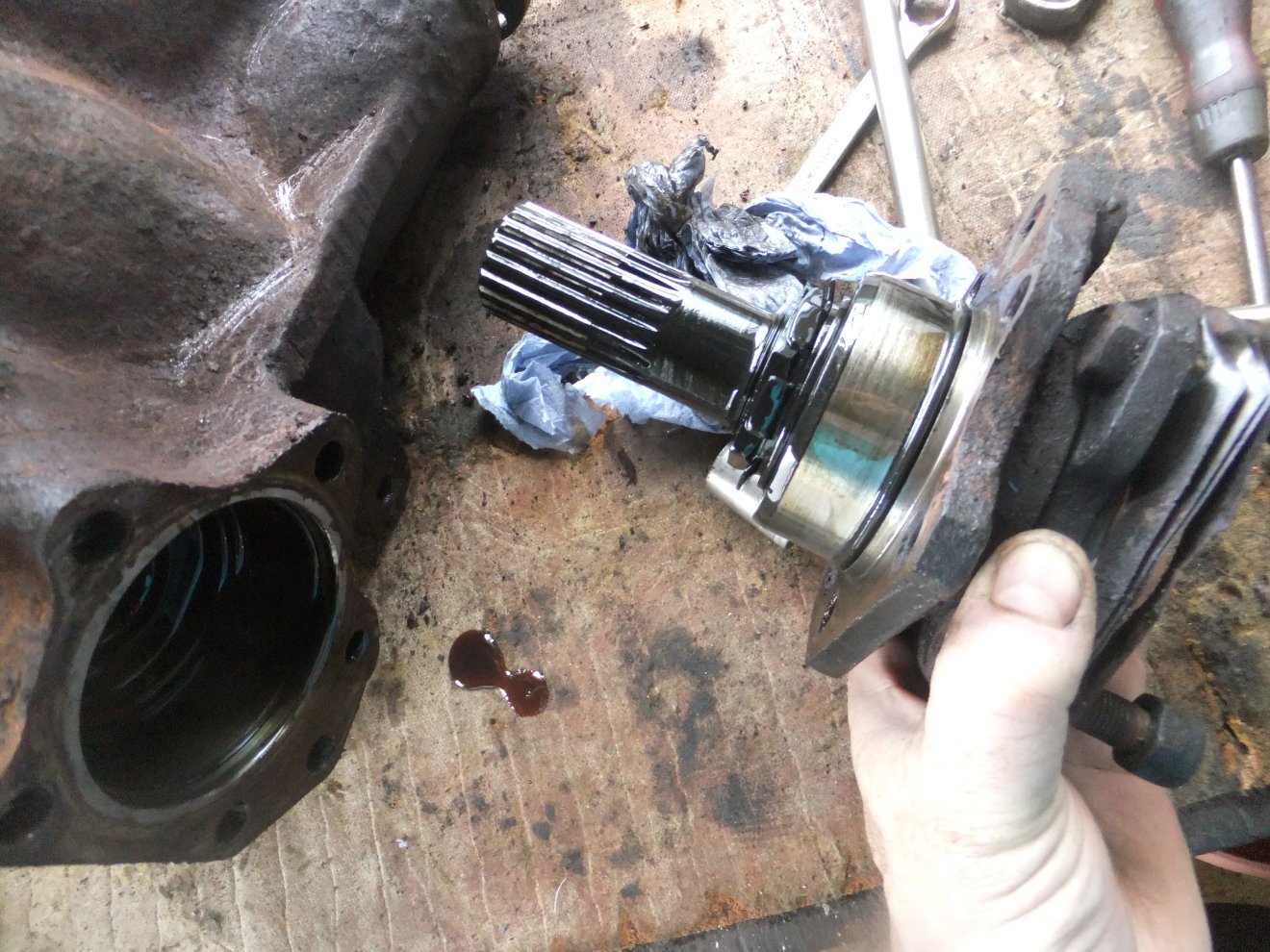
Each output shaft has an oil seal, the replacement of which demands a full strip of the shaft and housing assembly. In essence you bend back the lockwasher tabs (visible in the pic above), undo and remove the nut and lockwasher, push the shaft through the inner bearing, taking the outer bearing with it which catches and forces out the oil seal. Then simply reassemble (with new seal) in reverse order. There is the small matter of refitting the nut to EXACTLY the same position in order to avoid overtightening the bearings but as long as you mark (centrepunch) all the parts and carefully count the number of turns the nut takes to remove, it's not too challenging. What's that? You forgot to mark, or to count? Oh dear :D
Unusually for me, I was actually planning the order of work on this job, so whilst I was waiting for the new oil seals to arrive, I blasted some of the parts and resprayed them satin black.
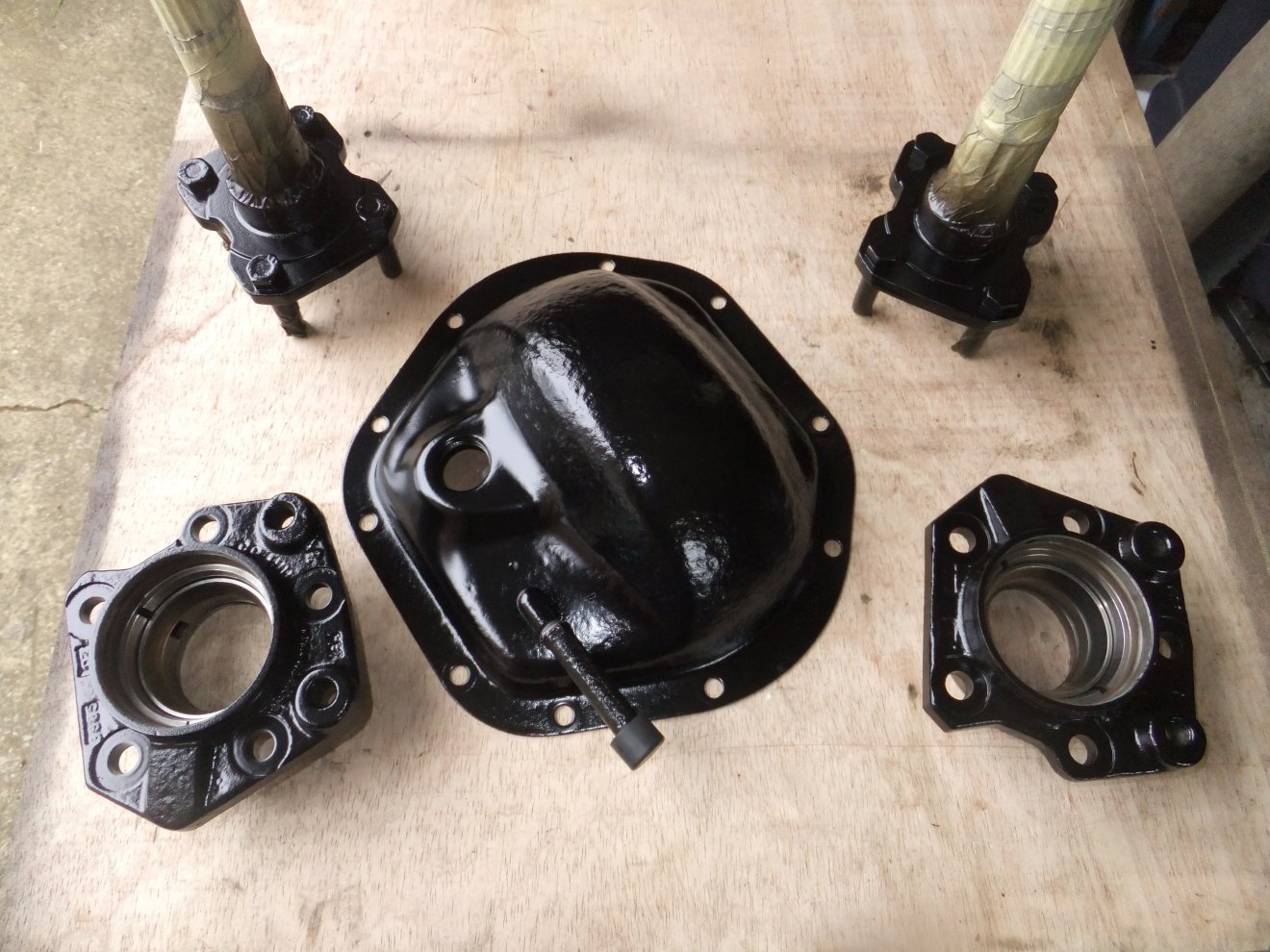
As you can see, I'd masked up the inner faces of the bearing housings so I wouldn't have to clean off overspray. The paint was Smoothrite satin which I usually find goes on quite well over bare metal, as long as you degrease it. The diff rear cover looks quite pock-marked due to corrosion but it's sound, there's a good thickness of steel there!
With the paint drying, I turned my attention to the third seal on the diff: the input (or pinion) shaft seal. As before, it's not too hard a job as long as you're aware of the 'approved' technique: the nut has to go back to EXACTLY the same position as before you undo it, otherwise there's a 'distance piece' between the bearings that will be either crushed too much or not nipped enough, either situation likely to lead to premature diff failure.
I started by centre-punching the input flange, nut and the shaft itself:
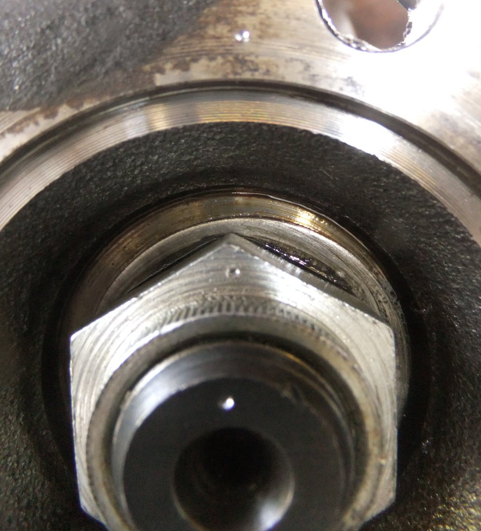
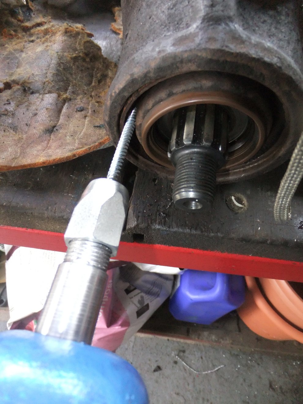
Then I held the flange (with a length of flat bar and two bolts) and unscrewed the nut, counting the turns until the thread disengaged. With the flange out of the way, I drilled a couple of holes in the old oil seal and used a slide hammer to pull the seal out:
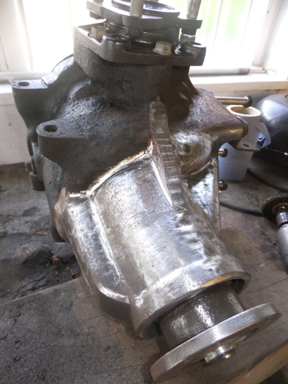
The new seal was carefully driven in, then once I'd fitted the new output shaft seals and rebuilt the assemblies, they were bolted back in and the rear cover replaced. Then it was time to make some mess! I fired up an air drill with one of those 'clean'n'strip' discs, plus my trusty 'Wizard' with an assortment of abrasive drums and carbide burrs. This represents about two hours' work; you can imagine how long the rest of it took...
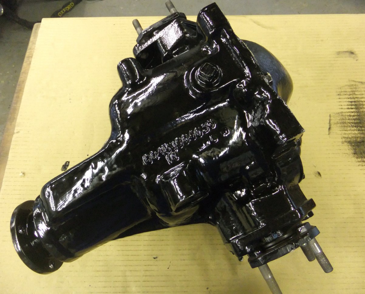
...but it was worth it once the paint was on! This is brushed Smoothrite, 4 coats of the stuff. I really don't fancy doing that stripping job again any time soon:
There's an exploded view of the Salisbury 4HU LSD on this page , albeit an earlier variety than this one, but it gives an idea of what to expect!
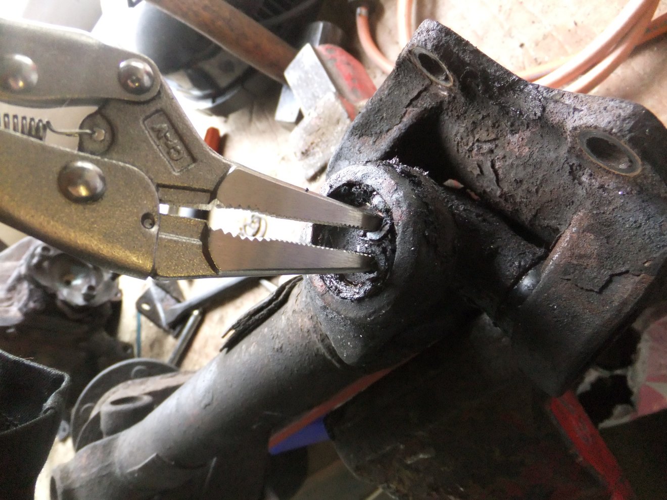
Next on the list were the driveshafts. I knew there was a bit of play in both inboard universal joints but it would be false economy to change the inners without doing the outers, so I attacked the bearing cap retaining circlips with circlip pliers. Nothing moved, so I got a bit more aggressive:
Eventually all 8 were out and it was time to wield a big hammer. In order to displace the bearing caps you strike the coupling yoke, which forces the lower cap out. Then you can turn the shaft over and do the same to get the second cap out (4-pound club hammer at right of picture):
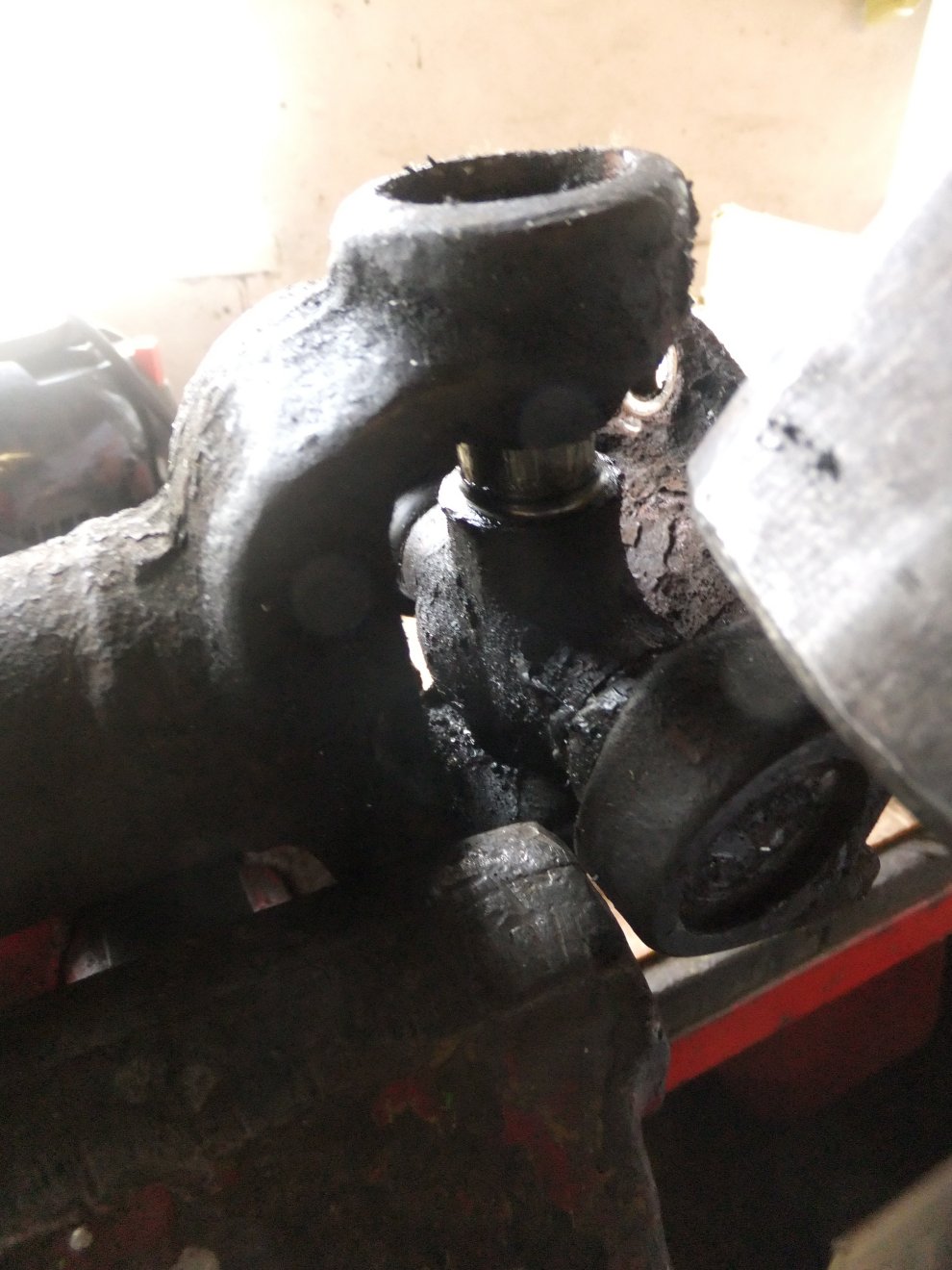
...leaving the coupling free. You can now use the vice and a couple of big sockets as a press to get the remaining two bearings out...
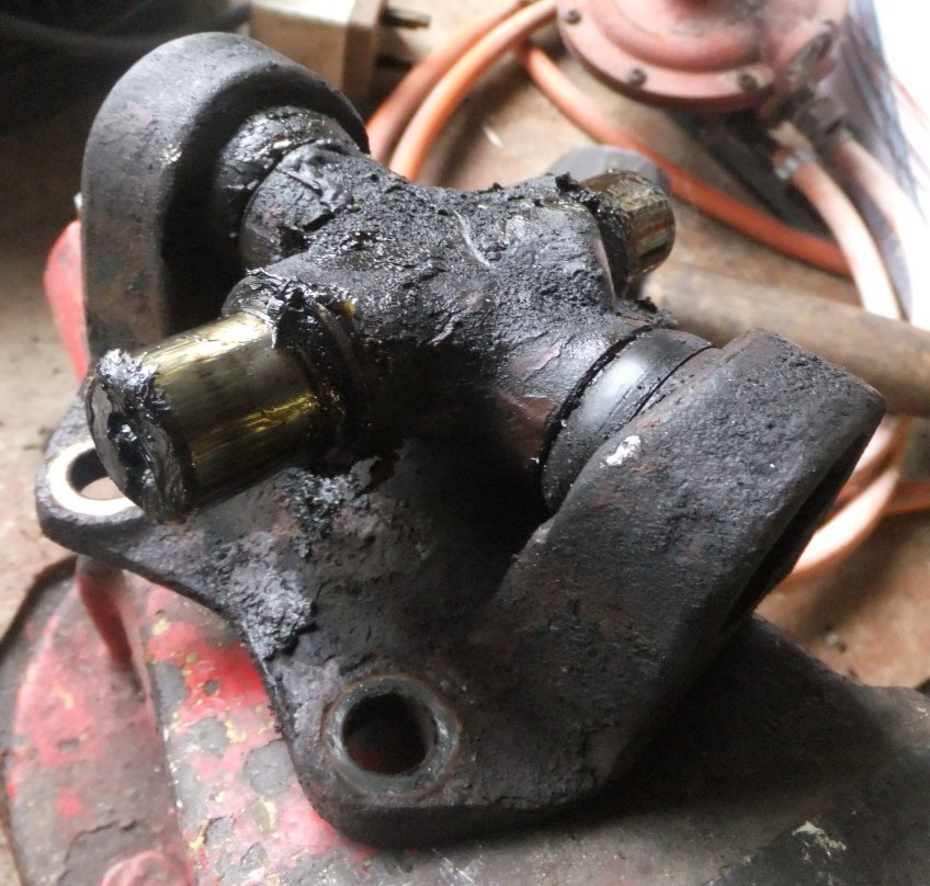
... and you'll then have a pile of claggy bits on your bench! Incidentally 'claggy' is a north-east England term for that which is a bit, well, claggy. A popular nickname for rough public houses is 'the claggy mat', being a pub where the carpets are so old and soiled that you stick to them as you walk. But I digress, so here's some clag:
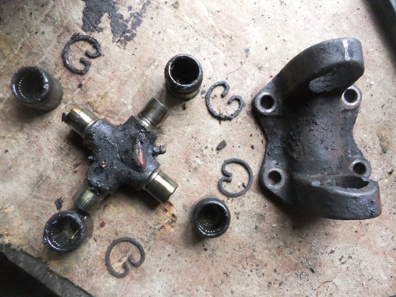
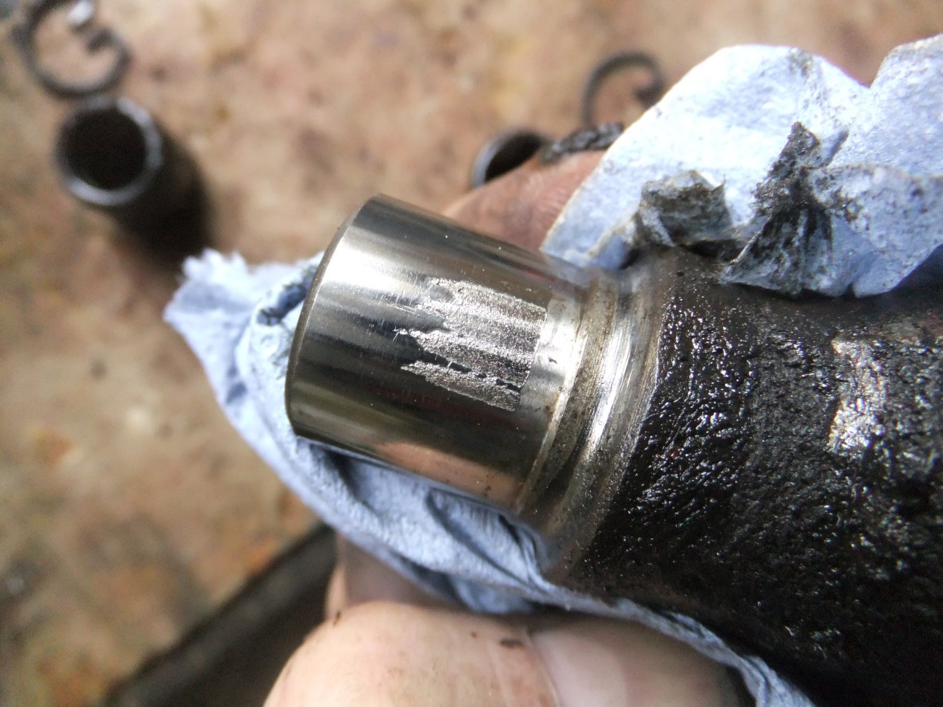
The cross-shaped part is the 'spider' or 'cruciform', you can see this one has a grease nipple fitted to allow you to add grease in service, which prolongs the life of the joint. You can be fairly confident the joint is on its way out if you see wear like this:
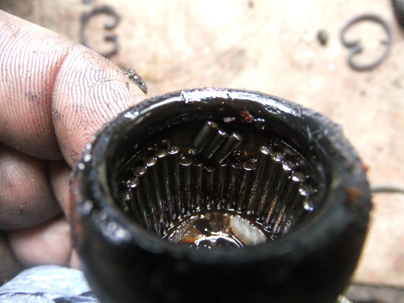
...or broken needle rollers:
The dismantled driveshafts were marked with centrepunch dots to help keep the original parts together at reassembly, then dunked in the parts washer for a good soak (see further down).
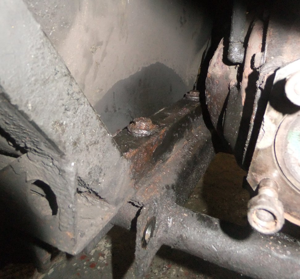
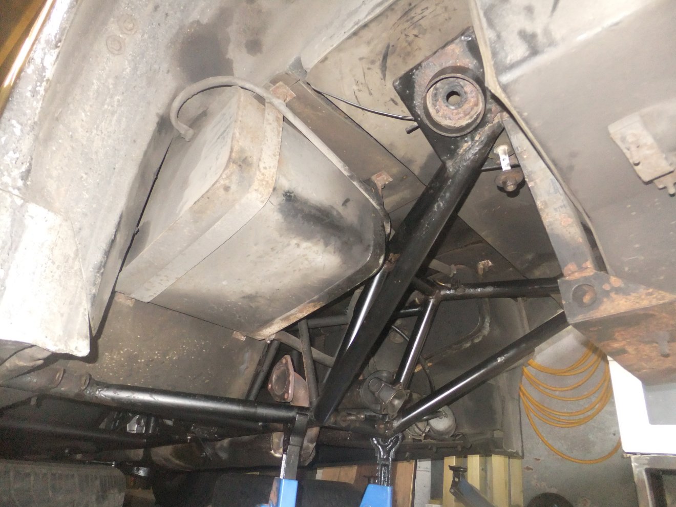
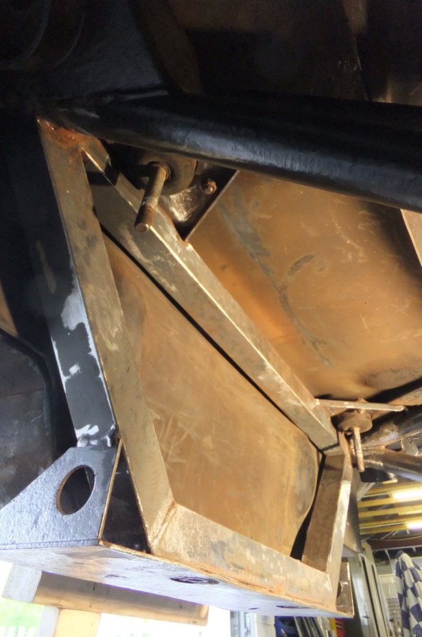
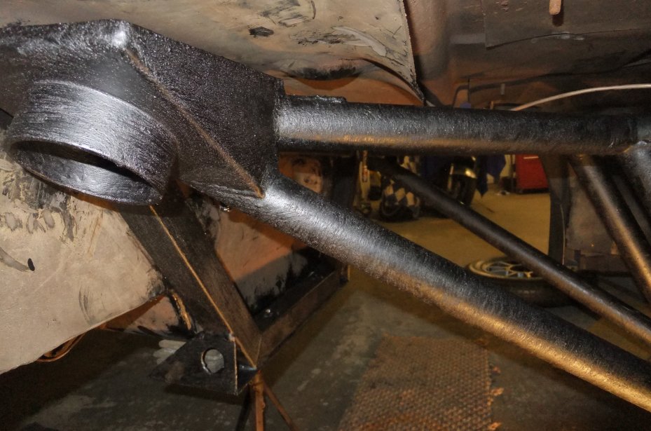
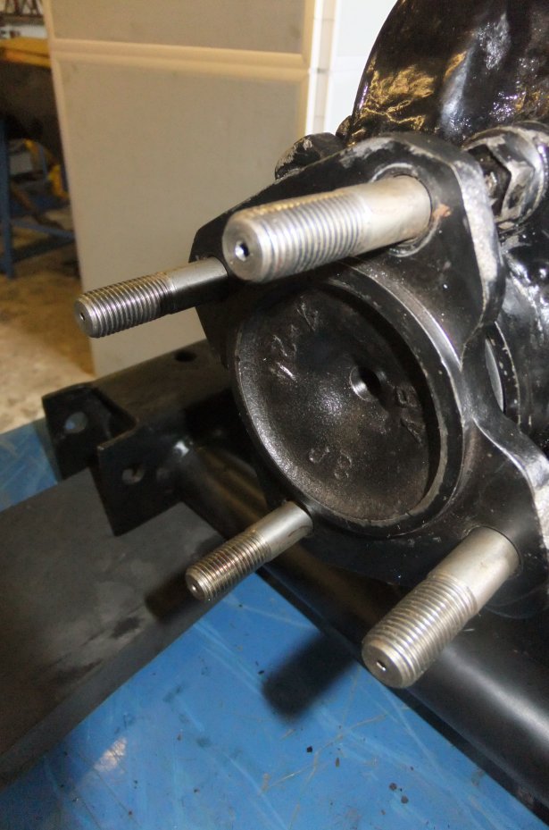
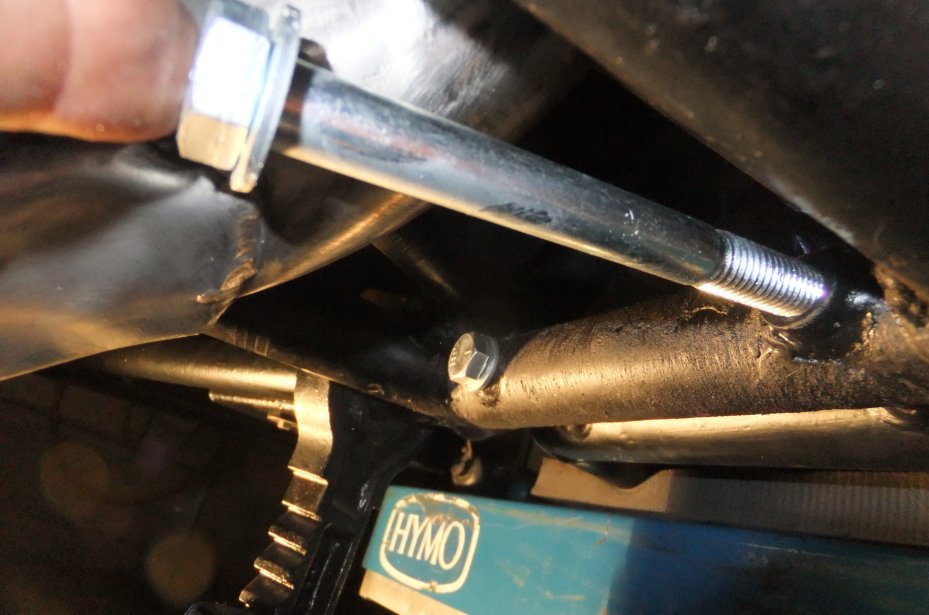
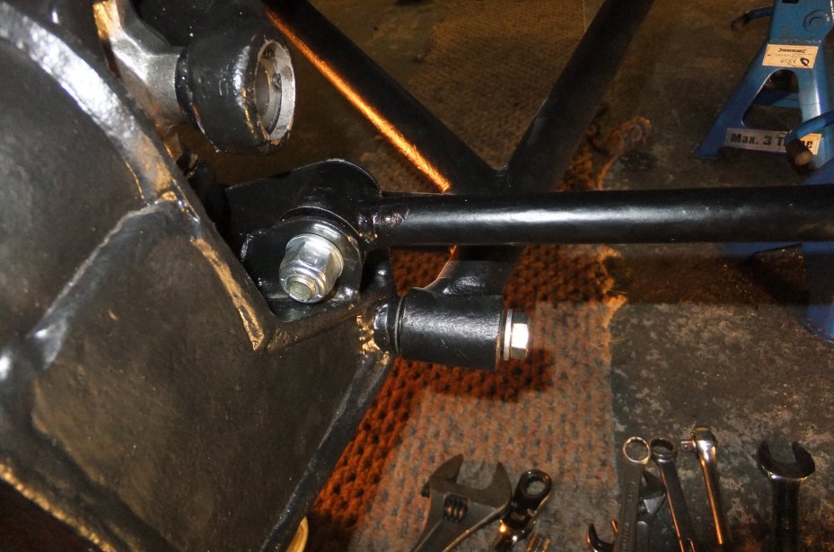
It was time to grovel under the car again, to resolve one of the problems I'd encountered when removing the differential subframe bolts. Or rather, NOT removing them as they were seized solid! Here are the offending bolts, seen from above with the diff. still fitted. Note that it's near-impossible to get a spanner or socket on these bolts with the driveshafts, brakes and A-frames fitted:
I'd managed to get the nuts off the bottom end of the bolts (itself no mean feat given where they are located, inside the length of channel that forms the rear member of the diff subframe) which let me get the subframe out of the way, so now it was time to get busy with an air drill to remove the bolts:
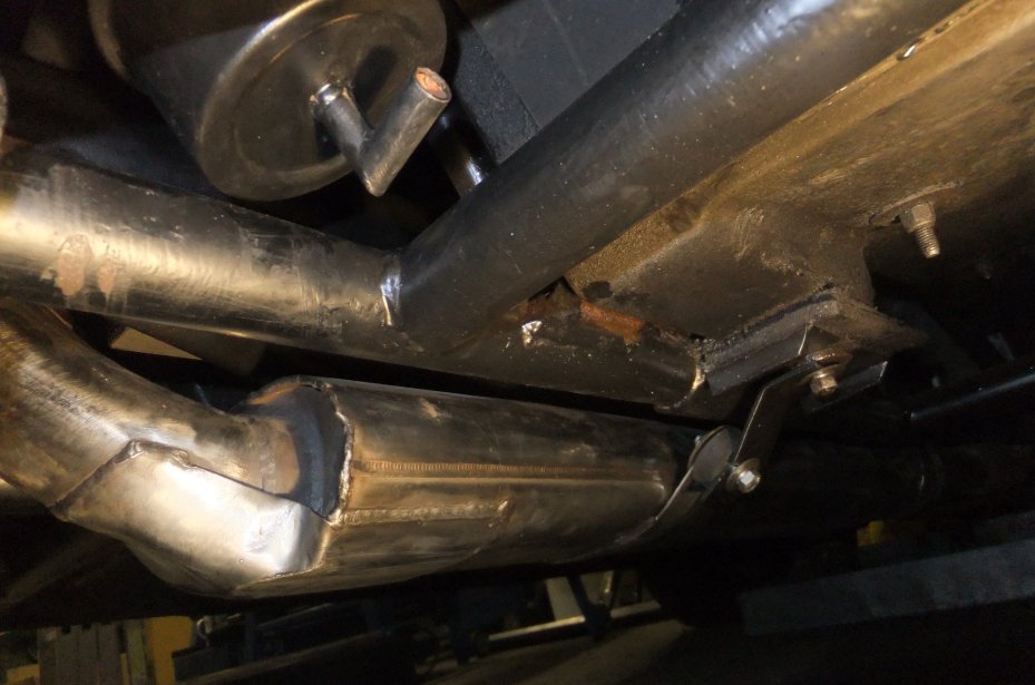
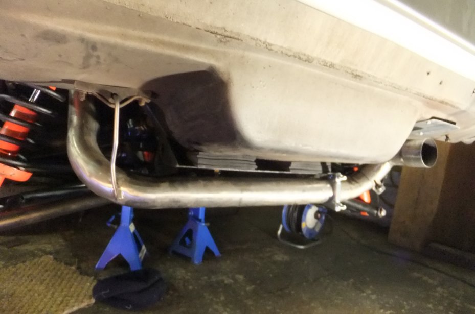
Whilst I was down there I took the opportunity to drop the rear section of the exhaust. It's stainless steel, though you wouldn't think so from this photo:
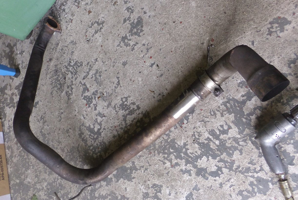
I put a stripping disc in that air drill and gave the pipe a once-over:
Another job done, but there was still plenty more to go; here are a few pics taken as work progressed...
The chassis after I cleaned all the crud off with petrol... needs a spot of paint:
The hub carriers, with bearings removed. Excuse the yellow paint, it was all I had late one evening about 10 years ago...!
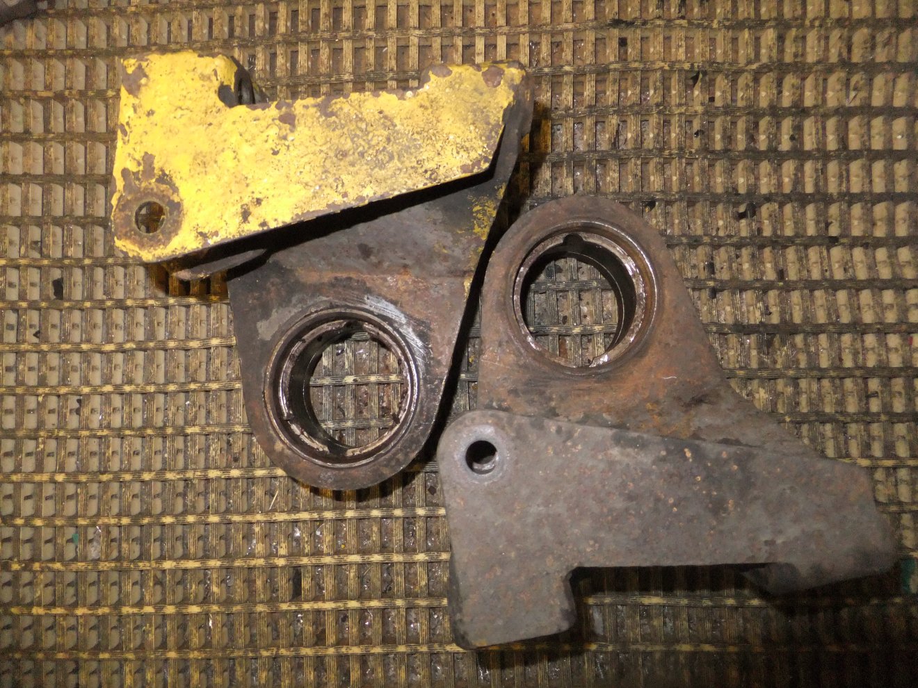
They looked a lot better after a session with some aluminium oxide!
Hubs and stub axles, post-washing:
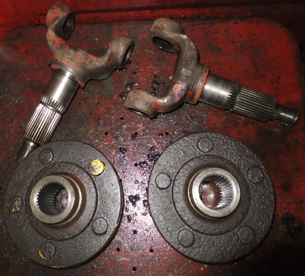
...and one of the half-shafts similarly treated:
Looking even better after a quick blast with some 80 grit (the rectangular plates are balance weights, in case you wondered)...

The long cold winter of 2012/13 was nearing its end (or so I thought) and as I wasn't making much progress with the suspension I thought I really needed to add to my workload by giving the fuel system an overhaul! It seemed to make sense; after all the fuel tanks were easily accessible with all the suspension out of the way and in all the years I'd owned the car I'd never even changed the fuel filter (it had been renewed just before I got the car and even after a dozen years I hadn't done much more than 20,000 miles it it). So one chilly Saturday I pulled the fuel pipe off the filter, directed it into a 20L container and switched the fuel pump on...
UPDATE October 2013:
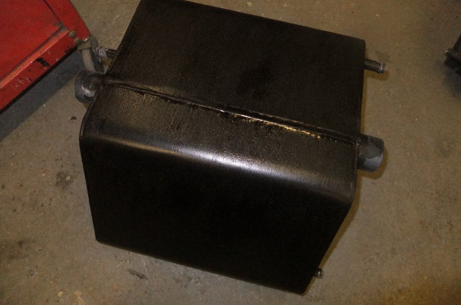
Well, so much for the long hot summer of 2013! I spent much of it working away from home and progress on the car was slow, probably not helped by one job leading to another. I began by dropping the fuel tanks out and immediately found a problem. The left-hand tank had a strange pattern on the top surface (the tanks are clamped against the underside of the floor which is lined with sheet rubber). Closer investigation showed that the tank had a pin-prick hole and quite extensive surface pitting over much of the top face. I realised that the frequent smell of petrol I'd noticed over the years must have been due to it leaking from the pinhole when the tanks were filled: I'd always assumed it was just the tank breather I was smelling! I stripped the muck, paint and surface rust away to show the extent; it's obvious that a sizeable repair will be needed and I've ordered some 1.2mm steel sheet with a view to letting-in a repair patch over the whole area.
Meanwhile, the fuel pump, filter and swirl pot were removed to the bench for a clean-up. The swirl pot has a reputation for corroding through but this one is fine. A new filter was obtained along with new hoses throughout... and this is where the next problem surfaced. The fuel lines run along the offside sill tube. I cut the cable ties and pulled the old low-pressure line out (it was quite badly perished) and then noticed an area of flaking paint and rust on the chassis tube. This was a tad worrying as I'd replaced the sill plates and cleaned up the tubes a few years ago; most of what could be seen from underneath still looked good, but this one patch looked quite bad. The only way to get at it was to remove the GRP sill cover. Luckily the stainless studs I'd fitted the last time it was off were sound, meaning it was a relatively painless job to pull the cover off... whereupon the problem was obvious. The front offside sill plate was disintegrating! To save repeating myself, you can see how I dealt with it here...
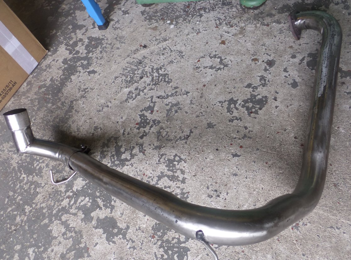
With the fuel pump cleaned up, the swirl pot repainted and a selection of new hoses ready to be fitted, it was time to crack on with other matters. Such as the exhaust system. You can see what transpired here...
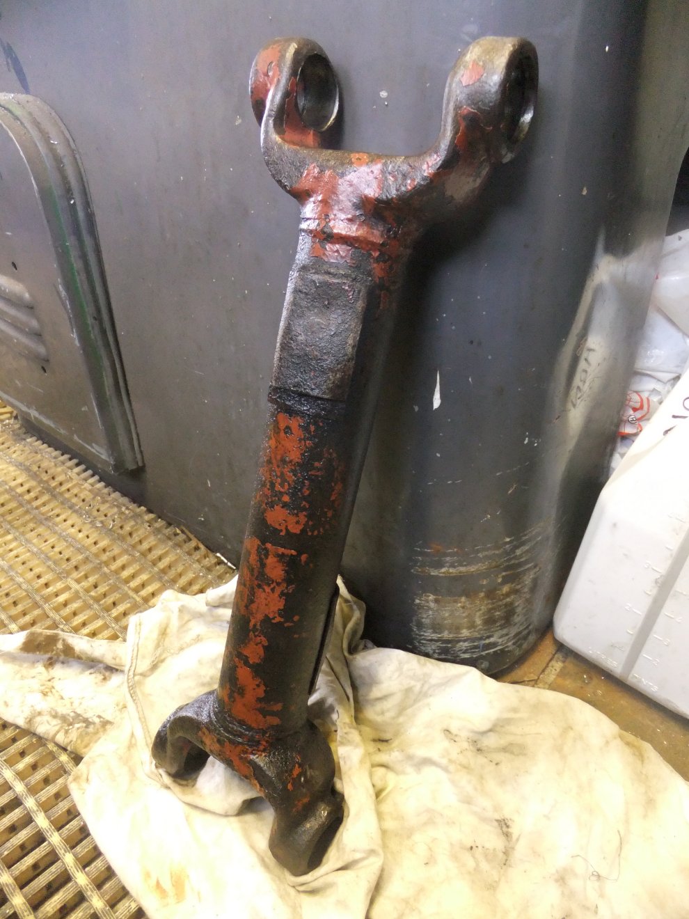
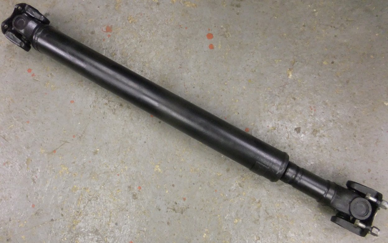
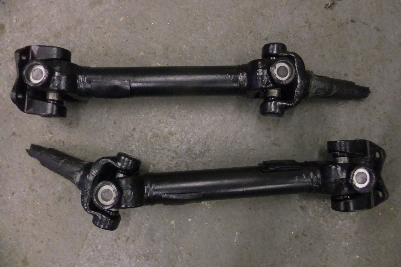
...and with the other sections of the exhaust cleaned back to shiny stainless, it was set aside to await refitting to the car. Leaving it off gave me better access to the chassis for repainting and, of course, to the propshaft, which was also removed for overhaul. A pair of new Universal Joints, a strip and repaint was an afternoon's work:
As you can see in the earlier pictures, I'd already sandblasted the driveshafts in readiness for paint or powdercoating. As they'd been sat for several months, surface rusting had taken place necessitating a further session in the sandblaster. I decided that painting would suffice so the splined sections and the bores for the UJ cups were masked off and the parts primed, then painted satin black. Once dry, new joints were installed:
The similarly-rusting hub carriers were also re-blasted and painted:
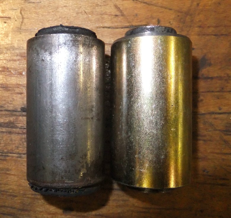
One of the things that took some time resolving was the issue of new bonded rubber ('Metalastik') bushes for the wishbones (A-frames in TVR terminology) and the lower differential mounts. They are, according to several sources including TVR specialists and internet know-alls, 'specials', 'unobtainable', 'obsolete', 'made in Lancaster' - and, of course the old favourite 'best replaced with Polyurethane'. My view of PU is best summed up as 'bollocks', and expensive bollocks at that. To be fair, extensive reading, calling and browsing (including contacting some of the former factory guys, now independent suppliers) did suggest that the original bushes weren't on a shelf anywhere easily to hand. But 'specials'? I doubt it. The bushes are Imperial sizes. I'd have thought that if TVR had approached a bush manufacturer in the early-mid 1980s and asked for a brand-new bush, then surely it would have been to Metric sizes? More likely, the bush supplier looked at what they had lying around on a shelf and off-loaded them onto TVR, rather than tooling-up for some oddball size. So no, I don't believe that these bushes are anything mystical. I'm fairly confident I've ruled out Jaguar and Landrover as donor vehicles; nothing on any Ford or Vauxhall that I can find is the same so I suspect they were probably used on a milk-float or the Sherpa van or something equally bizarre - and as Lancaster isn't a million miles from Leyland, who knows? ;o) Speaking of Leyland, with typical British motor industry cheapness - sorry, ingenuity - the original Sherpa was built using lots of bits carried forward from earlier vehicles, all of which used Imperial fittings. Years later, rebranded as LDV, a lot of bits were changed to Metric sizes.
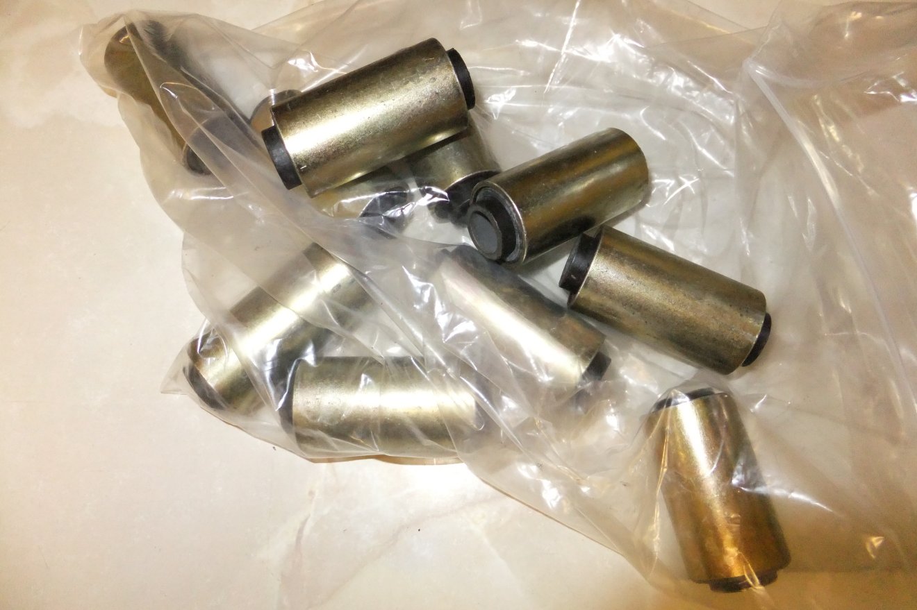
Anyway, I couldn't find anything off-the-shelf that would fit. But I could find suppliers of bonded bushes, including Trelleborg who now own the Metalastik brand. Despite the massive range of sizes they stock, I couldn't find exactly what I wanted - but I did find something that has the right inner and outer diameters, just too long. Still, where there's a lathe, there's a way, so I stuck my neck out and ordered ten bushes.
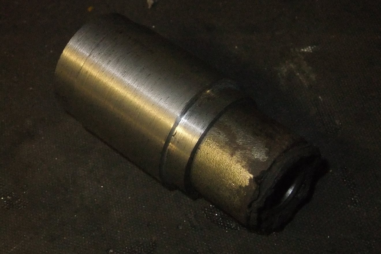
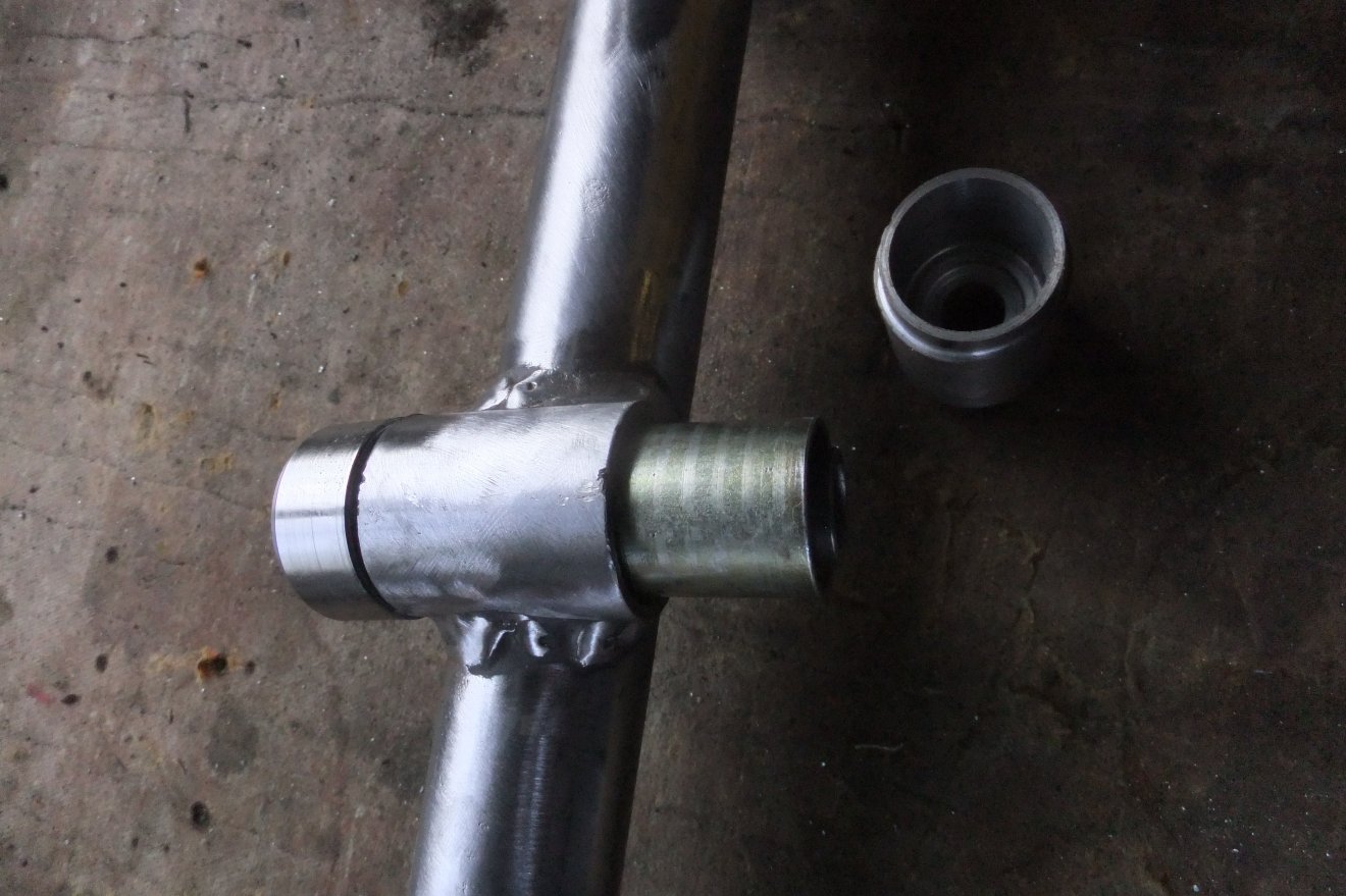
Some time was spent carefully shortening the bushes to match the originals (shown here, before):
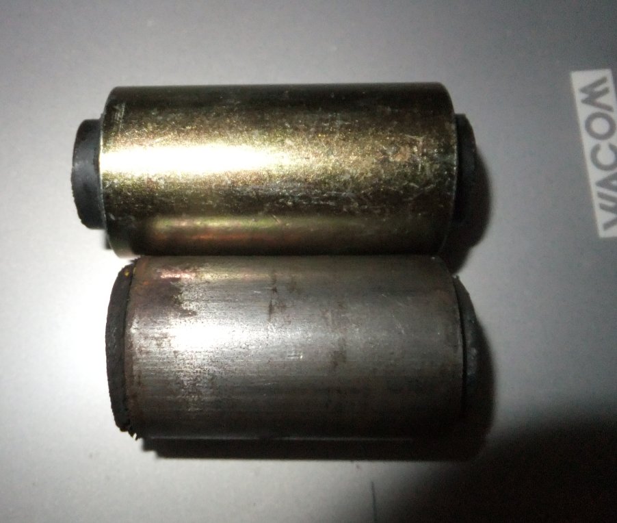
and after modification (note the 'lead-in' chamfer I added):
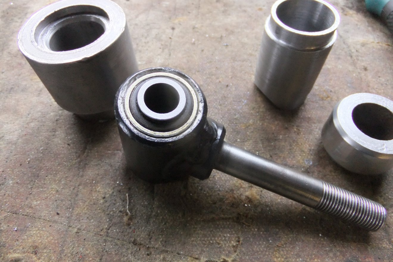
I then made a set of press tools to help me get the new bushes in without distorting them (last time I tried this job using the 'traditional' pair of big sockets, on my Esprit, I squashed a couple of bushes out of shape and had to buy more new ones):
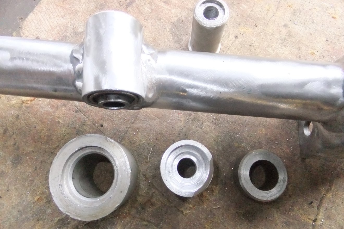
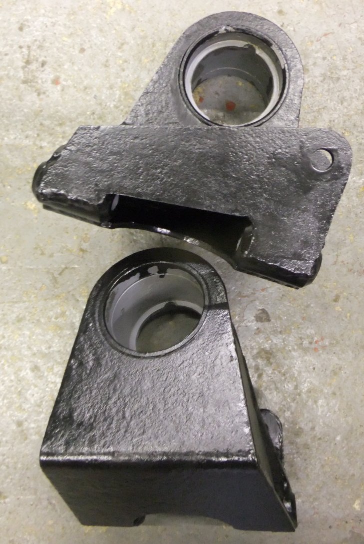
The A-frames and the diff. subframe were stripped for repainting, then the new bushes pressed-in. The machined spacer (at left) protects the bush 'eye' from damage by the vice jaw:
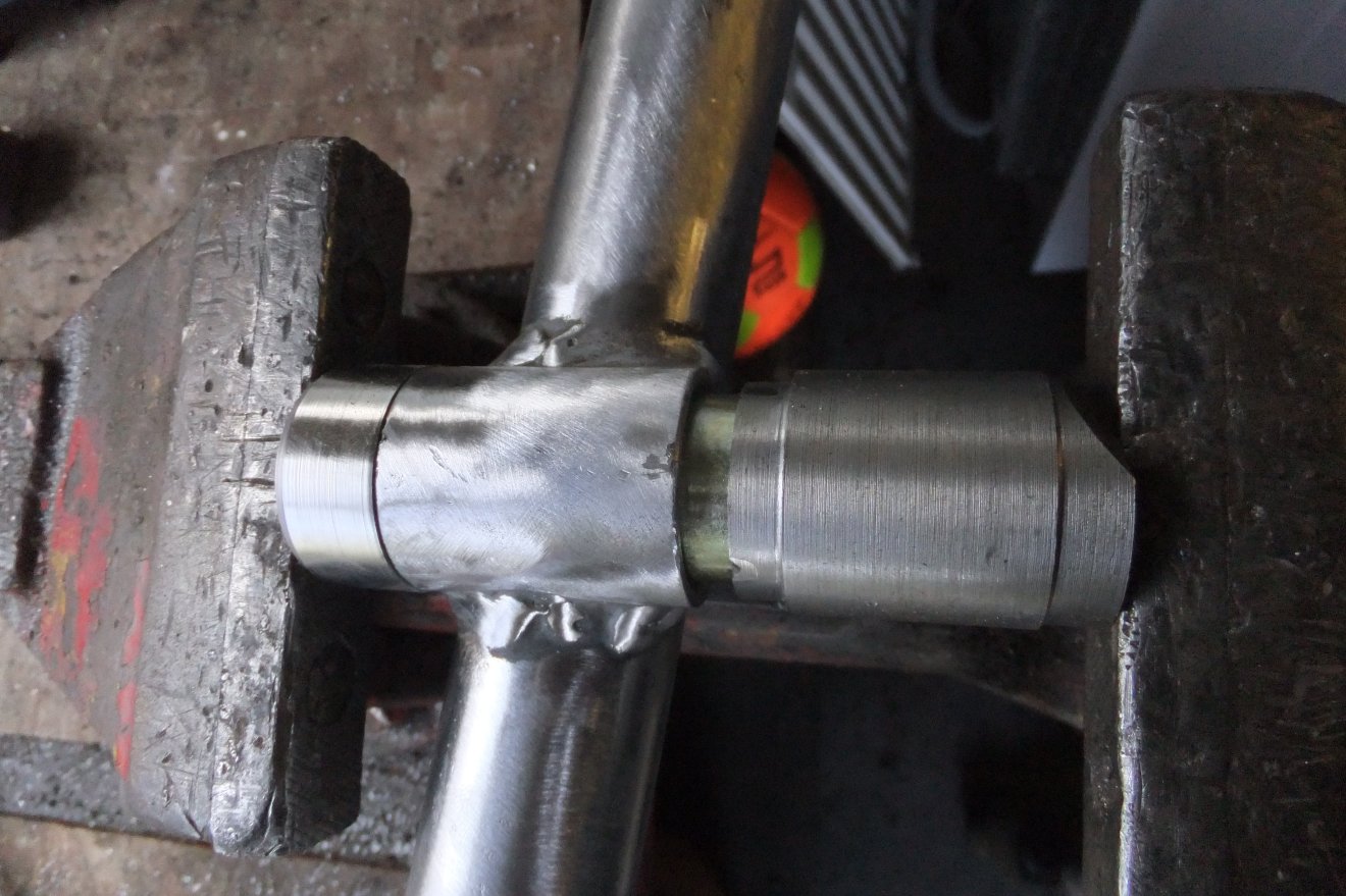
You can make out the stepped bore of the 'driver' piece at right (pic below); the step ensures that the driver is pushing only on the bush outer sleeve and not the inner:
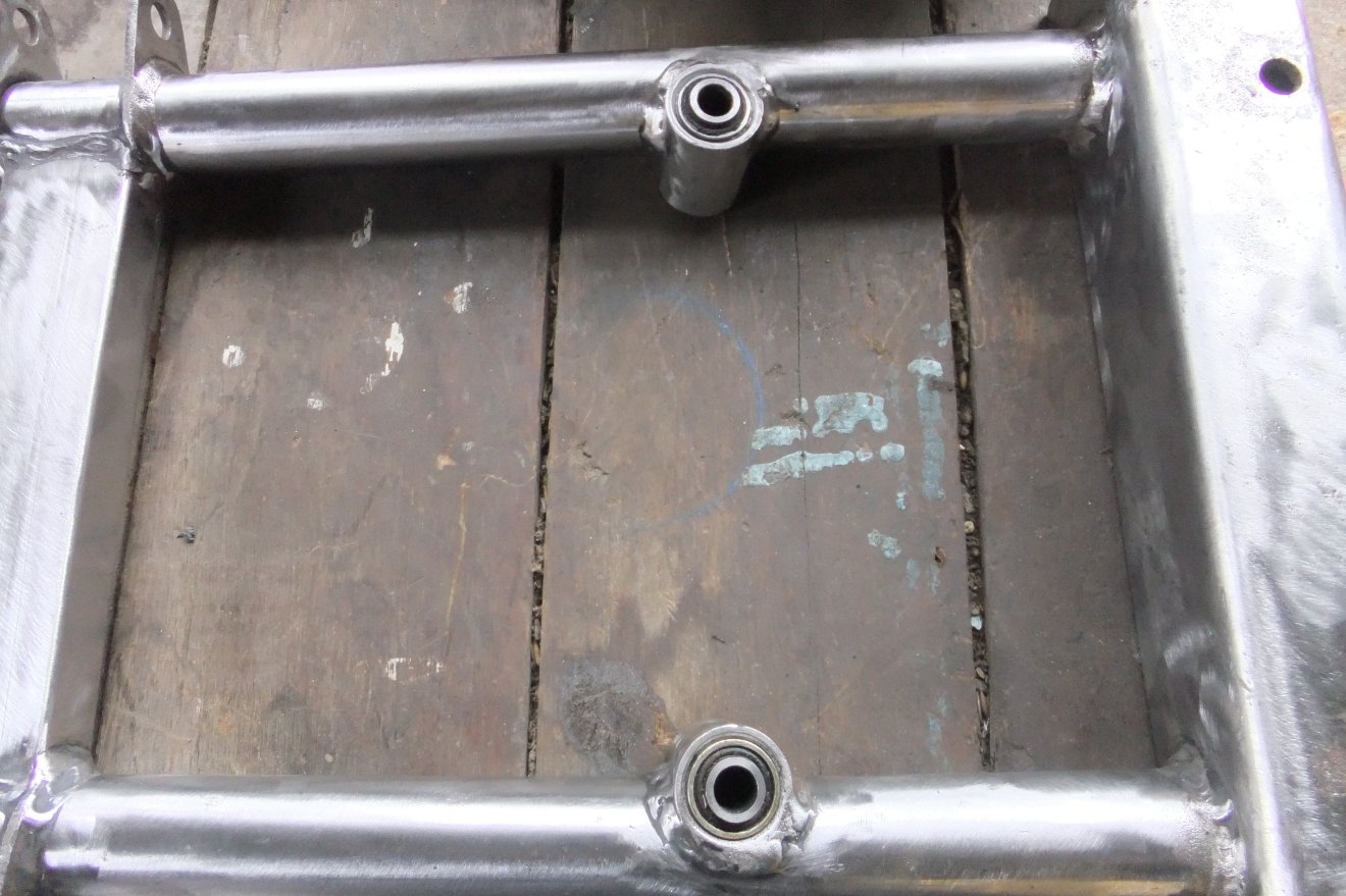
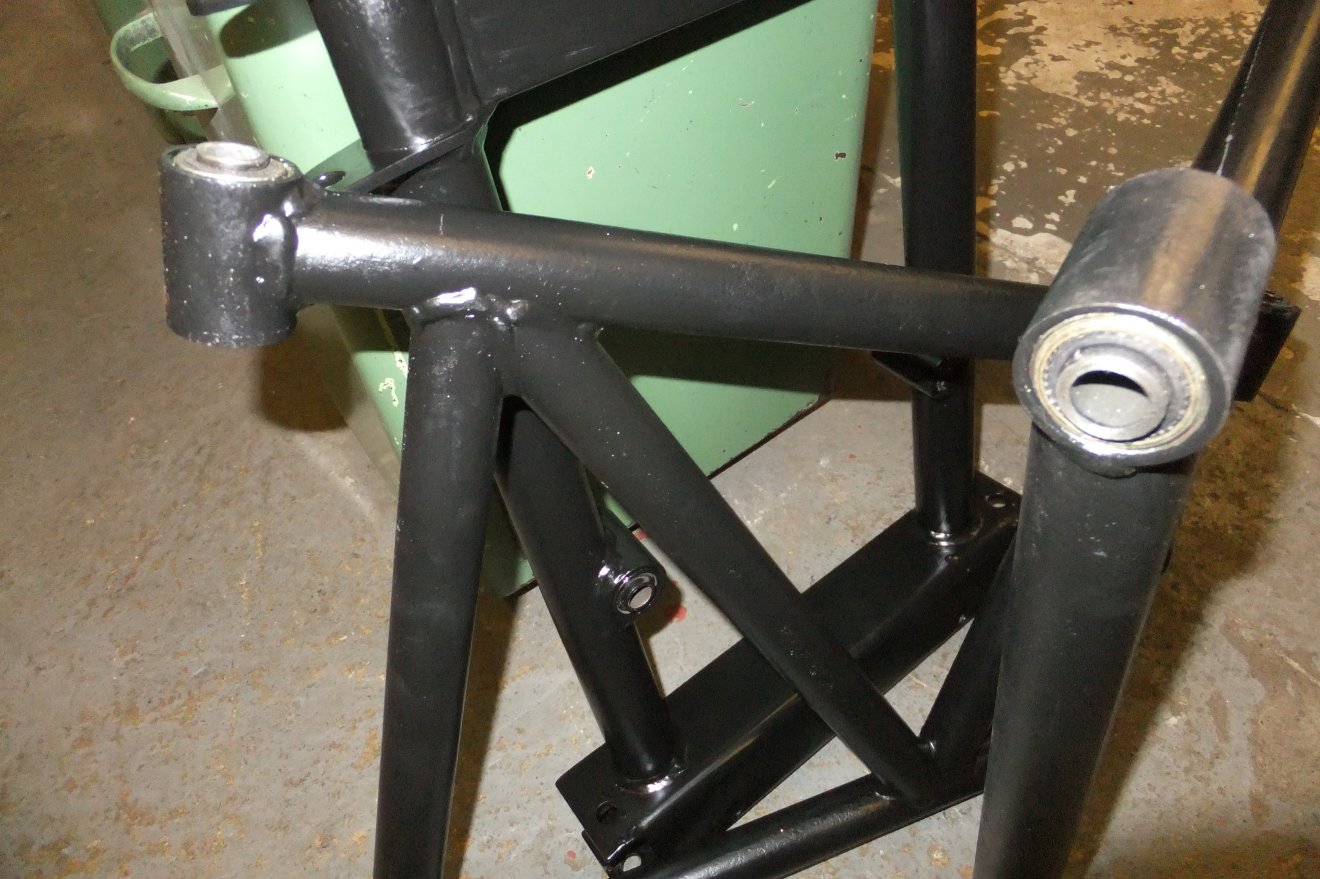
All bushed and ready to go :D
I summoned up the boredom tolerance necessary to stand and sandblast the coil springs, then intead of painting them I remembered my powdercoating kit that hadn't seen the light of day since I coated various bits for the Esprit, some 7 years earlier! I now have a decommissioned domestic oven (i.e. new kitchen fitted!) that is just big enough to take the springs, so they were hung precariously from the workshop rafters, satin black powder wafted over them and they were baked for about 30 mins at 180 degrees. Results aren't too bad (bit crunchy, not enough salt):
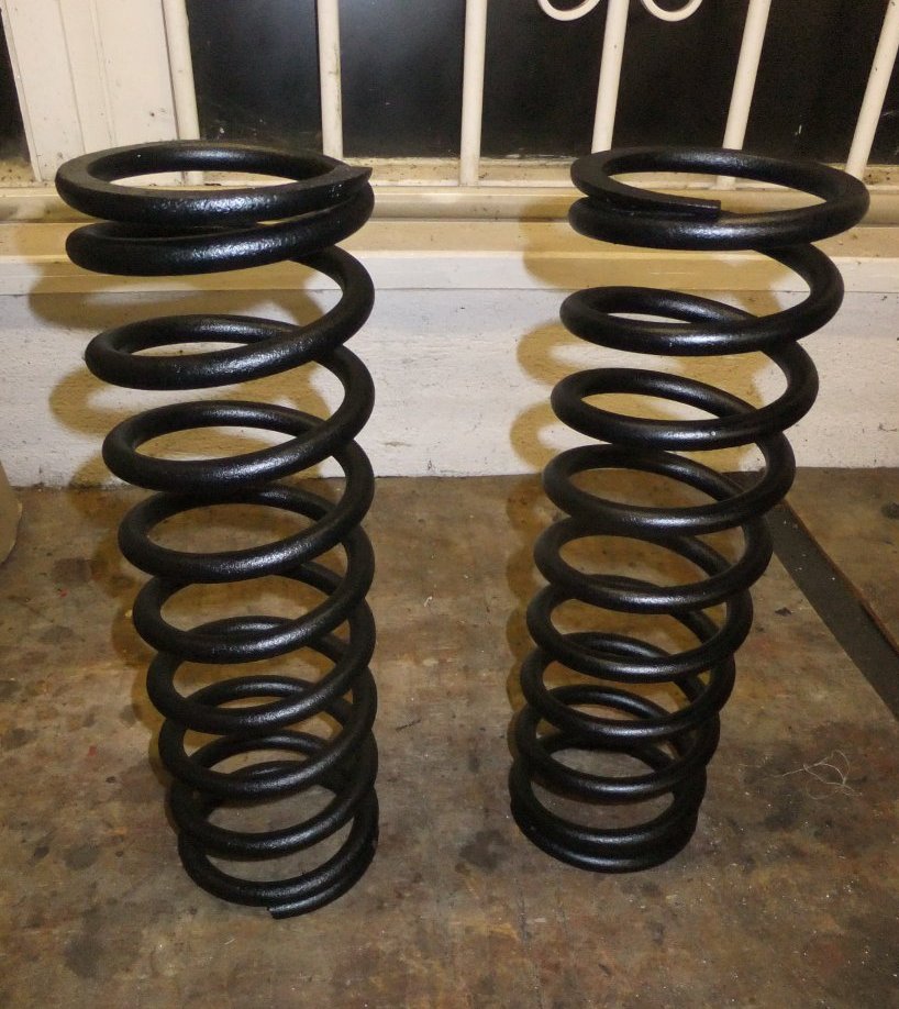
I still can't achieve that thick glossy coat that the pro's do so the texture you can see is largely due to the pitting in the steel! Curiously, one spring has an overall worse-pitted appearance than the other so I wonder whether one has been replaced or maybe the nearside one gets more water spray off puddles in the road...?
As this page was getting a bit long I've moved the saga of the leaking fuel tank here...
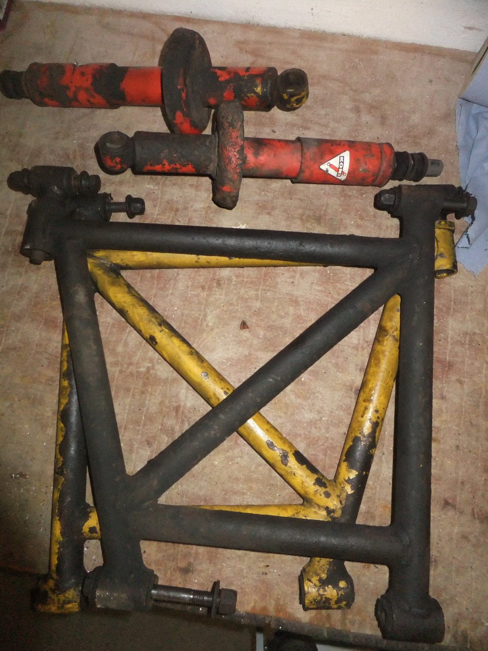
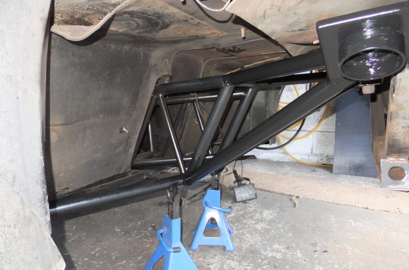
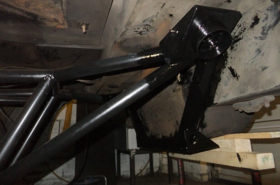
Next on the refurbishment list were the rear dampers; I replaced the ones I took off with some less scruffy items that nevertheless required a strip and repaint (I even got some replica Koni decals to go on them!). As another summer drifted by (2014) I spent more than a few hours of it lying on my back attacking the chassis tubes with an assortment of abrasives, followed by degreasing and painting. At time of writing this there wasn't much left to do, but what there was happens to be the most difficult areas to get at... the box-section tubes forming the rear diff cradle support and also carrying some sheet metalwork that holds up the bodyshell (extreme right of this pic):
This last bit of the chassis was eventually cleaned up...
...and painted (and knowing what I know now I'd have used Jotun Jotamastic 90, so there's a recommendation):
Then a coat of underseal was applied for good measure, albeit not concours appearance:
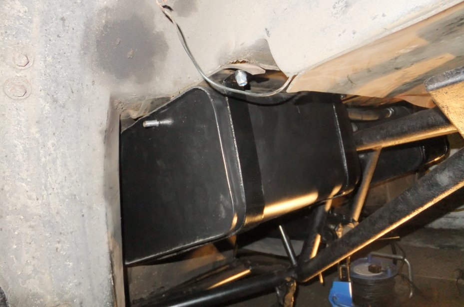
I also undersealed the top and front faces of the fuel tanks (where they meet the rubber matting glued to the underside of the car)...
before they were refitted, along with all new fuel lines, filter, hose clips and wiring sub-loom to the pump:
You can just see that the propshaft had also been refitted at this stage, it was easier to do that before installing the exhaust silencer. The silencer hangers were powder-coated and new rubber bobbins were obtained; bizarrely nowhere that I tried in the UK had the particular size I wanted but I managed to get a pair from an Ebay seller in Germany (good price as well).
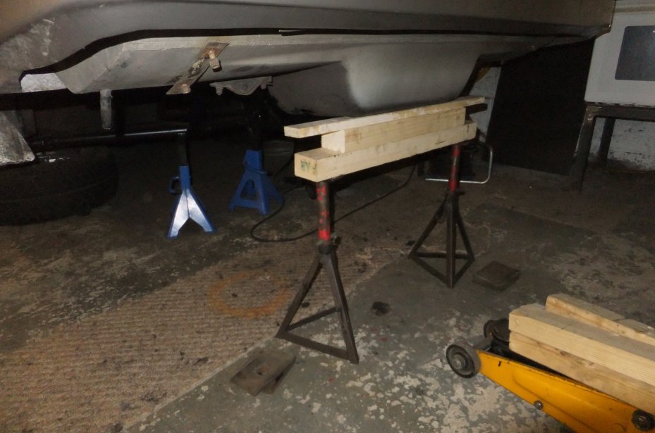
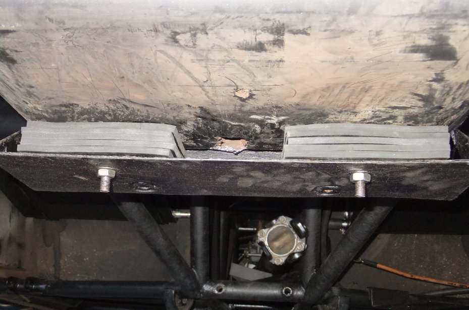
Returning to the rear of the chassis, the bodyshell is packed-up to level it using slabs of thick rubber and a pair of bolts through the boot floor. I needed access to the chassis for cleaning and painting so I removed the bolts and packers and arranged a temporary trestle of axle stands and wooden offcuts, giving just enough room to wield my latest pneumatic acquisition: a needle de-scaler!
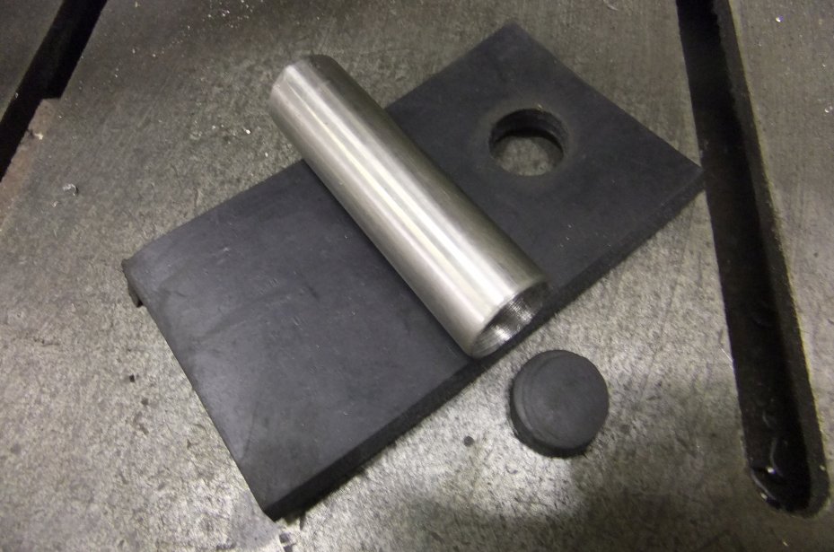
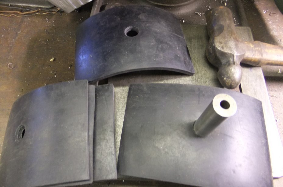
As the rubber packing was perished and seemed to have been crushed somewhat, I thought that replacing it might lift the rear end of the body and perhaps help the doors to close a bit better. Off to Ebay for a sheet of 6mm rubber (hint: the more you buy, the cheaper it gets. Whether I can find a use for the remaining 1.8 square metres remains to be seen...) which was easily cut into neat rectangles, but then I had the problem of putting holes through each piece for the bolts to pass through. I fired-up the lathe and made a simple wad punch that, with a couple of swift taps of a hammer, made a neat hole:
I slid one piece into place on the car, marked it to show where the bolt would be and then used that piece as a guide to perforate all of the others:
A couple of new bolts later and the shell was clamped back into place...
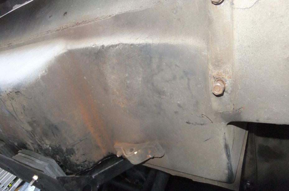
With the 390SE's distinctive 'under-wing' removed for access to the chassis, I found an area of the fibreglasss shell just above the tailpipe had been affected by the exhaust heat, the gel-coat leached away leaving bare fibres (visible just above the rubber exhaust mount):
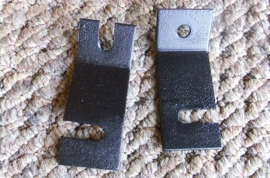
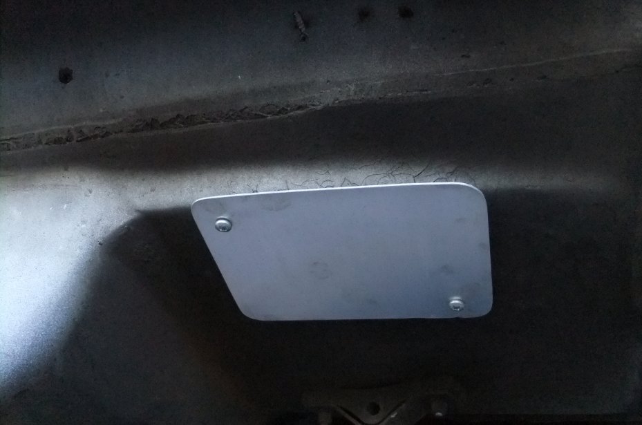
A bit of scrap alloy plate was soon transformed into a heat-shield that should be near-invisible once the wing and exhaust are back on:
The differential was reunited with its cradle...
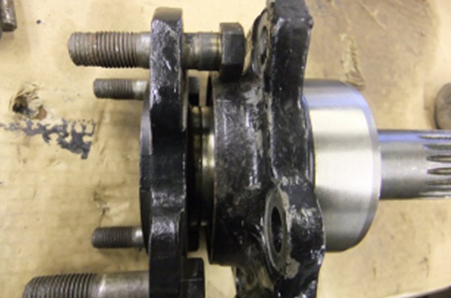
... at which time I remembered that one of the things I'd intended to do when it was stripped-down was to renew the output flange bolts on the right-hand flange (the left-hand ones are OK but the right-hand were in a shocking state of corrosion and vanished threads). I tipped the diff. onto its side and once again removed the stub axle assembly:
Not a brilliant photo but you can see that the threads are Donald. (Ducked :D) Needless to say, these are no ordinary bolts: the thread's common enough but the shank just below the hex head is wider to make them an interference fit in the flange holes. Just for reference, a set of 4 bolts was £23 (Oct. 2014). Jaguar Heritage Parts supplied them and you can opt for free collection from your choice of Jag dealer. While I'm on, I may as well point out/ remind you that the correct nuts for this application are NOT Nylocs (as my car had fitted, bloody monkeys) but 'stiff nuts', aka Philidas nuts, a set of 8 of which will set you back another three beers'-worth of paper money (probably only two beers if you're 'darn sarf' :D).
Sometime after publishing this page I was contacted by fellow 'wedger' Andy Lovett who suggested I point out that Jaguar over the years/ models used different versions of these bolts, with about 5mm difference in the length. The correct (i.e. longer) type used here have the part number JLM442, as used on the XJS.
Now, you can forget simply knocking these bolts out of the flanges, the stub axle bearing housing is in the way whichever angle you try it. However to fully-strip the assembly again risks trashing the outboard oil seal, obviously not a problem if you do it the way I didn't and fix all the faults in one go... so I resorted to removing the locknut and inboard bearing, which gained me just enough wiggle-room to be able to knock the bolts past the housing (sorry, another poor photo):
Luckily it was a case of 'reassemble in reverse order' and I was able to tap the new bolts in and reassemble the stub axle assembly before bolting it back to the diff. and heading off to the pub :D
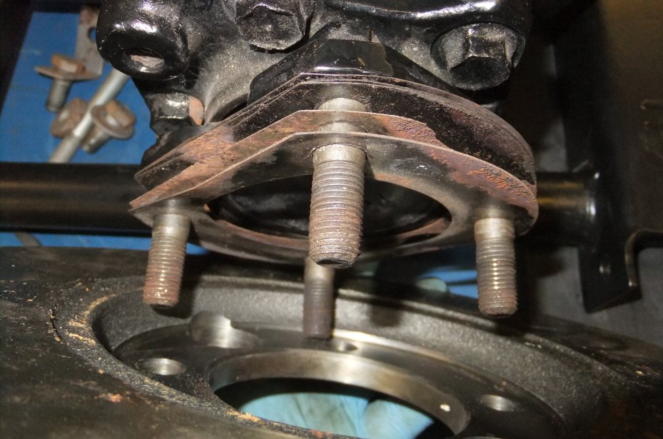
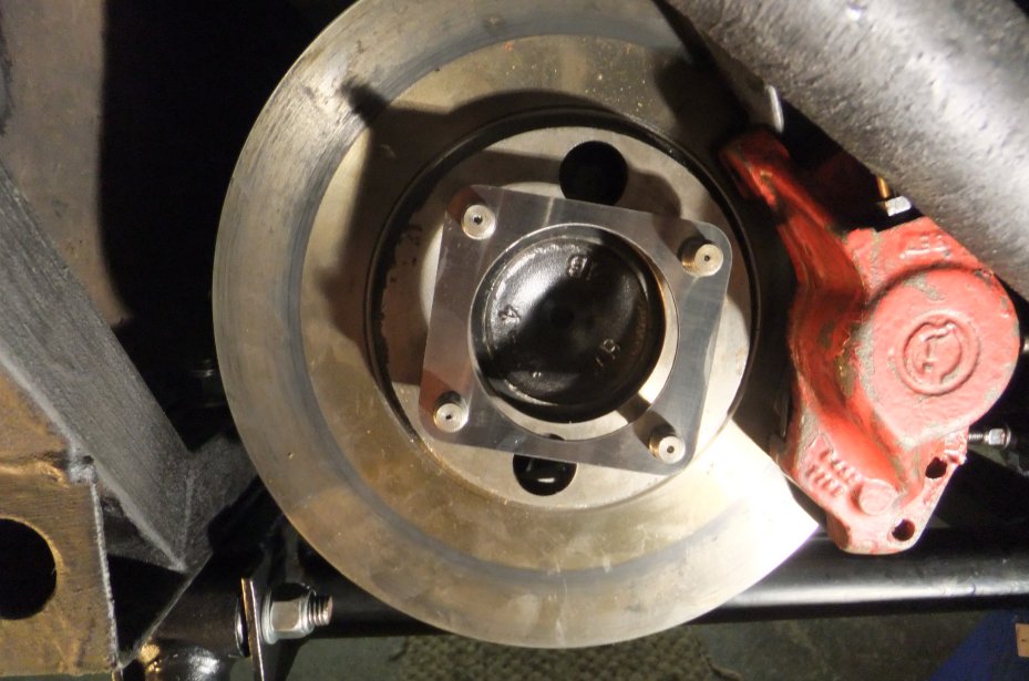
Next, it was time to start reassembling the inboard brakes. Firstly the discs have to be fitted and they have to be centralised in the calipers. The position of the disc is controlled by a stack of shims fitted to the diff's output flange before the disc is located over the studs (NB rusty shims installed for illustration!):
The disc is then positioned and temporarily secured with a stack of washers etc. and old nuts to clamp the disc firmly to the output flange.
The few rust spots are remarkable considering I bought the discs several years earlier and they've been sat in an unheated garage! The hydraulic calipers are then offered to their mounting flanges and the bolts inserted. This is where the fun begins as the space between the caliper and the side of the differential is very limited, more so on the right-hand side owing to the offset in the diff. casting.
There now follows a period of trial and error (perhaps with some measurement thrown in for good measure ;)) whereby you establish the correct thickness of shims required to centralise the disc in the caliper body:
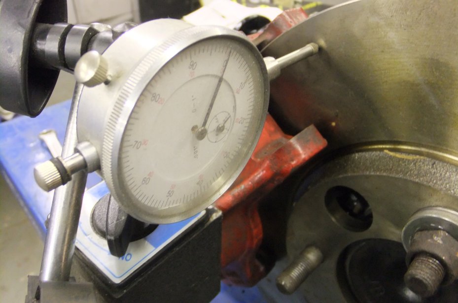
It's also a good idea to check the disc for run-out by mounting a DTI in a suitable fashion and rotating the diff input flange whilst observing the gauge; ideally you want zero deflection but the usually-quoted tolerance is 0.006" (six thou) maximum.
You can then proceed to mount the handbrake calipers to the hydraulic units: I've fitted better-quality pads and new pull-off springs this time and also replaced the steel link pipes between the caliper halves as well as remaking the rigid line up to the flexi hose, all in CuNiFe:
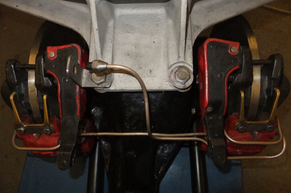
Also shown fitted is the alloy top carrier beam and the bracket that supports the brake flexi hose from the chassis.
At this point (end of November 2014) the entire diff. subframe assembly was ready to be lifted back into the car. Rather than performing balancing acts with trolley jacks I opted to use my scissor table to take the strain; there was just enough clearance for the diff's top beam to pass under the chassis tubes...
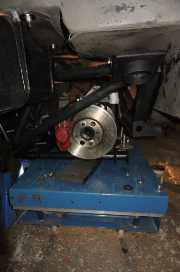
With an eye on the future I installed the rearmost lower carrier bolts so that the nuts would be at the top, which meant using a couple of offcuts of cardboard to keep the bolts in place as I lifted the assembly:
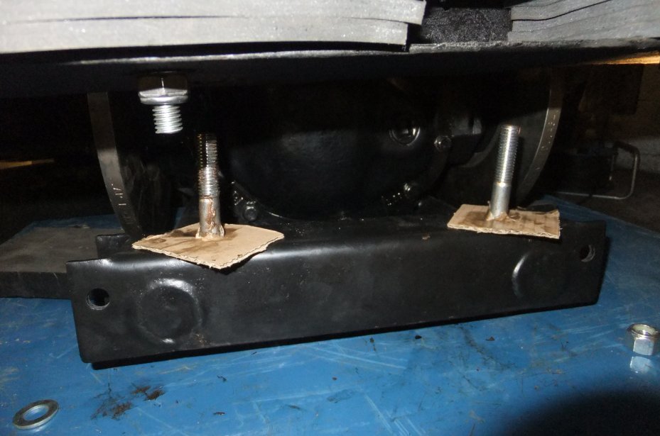
It was then a fairly simple matter of pressing the 'UP' button and wriggling the diff around until the various bolts slipped into position; the two through the top carrier were first in and had nuts screwed on a couple of turns...
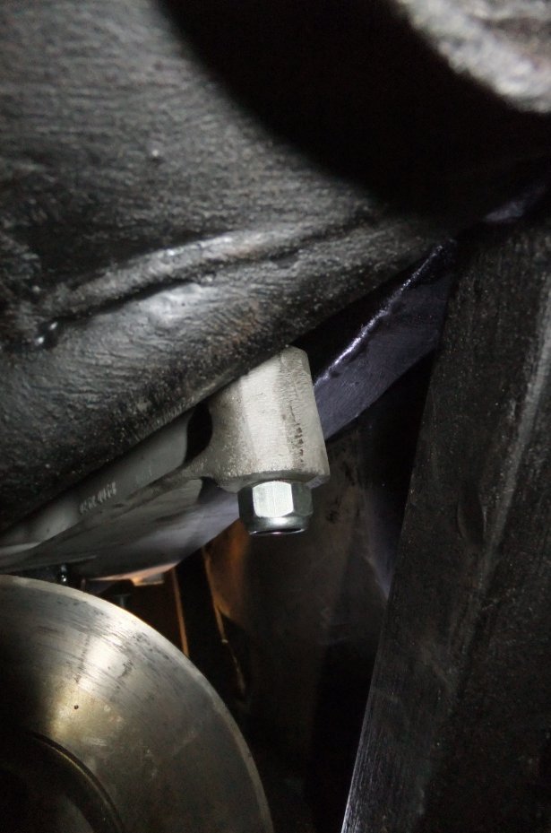
... then the lower rear bolts and finally the two front ones ( note copper grease on the other bolts, this one was greased after the photo was taken):
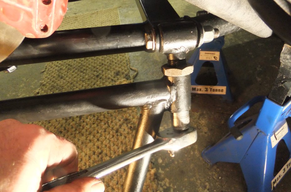
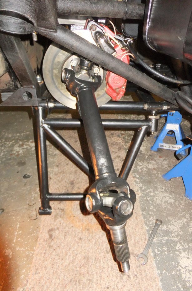
The next stage of the job was to reconnect the brake hydraulics and bleed the system, plus attempt to set-up the handbrake calipers. Cutting a story short, I found that the self-adjusting ratchets worked rather too efficiently and kept winding the pads into contact with the discs... which makes me wonder if that was the cause of my repeated brake failure episodes. I removed the ratchets, set the pads so they cleared the discs by a sensible amount and rediscovered the old problem of the Wedge handbrake running out of travel before the pads were stopping the wheels from moving. I decided to return to the problem at a later date and pressed-on with reassembling the suspension (albeit knowing that future access to the brakes would then be made more difficult!). The offside A-frame went quickly back in with new bolts:
... and the toe adjuster was set so that the A-frame was back at approximately the position I'd measured when I took it out...
Next, a stack of shiny new camber adjustment shims was slipped over the diff output flange bolts; the total thickness was an estimate based on the crusty remains of the old ones and will probably need altering once I have the suspension alignment checked:
The half-shaft was fitted, with new 'stiff nuts' (or Philidas nuts as they're also known)...
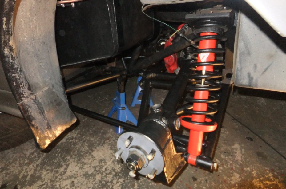
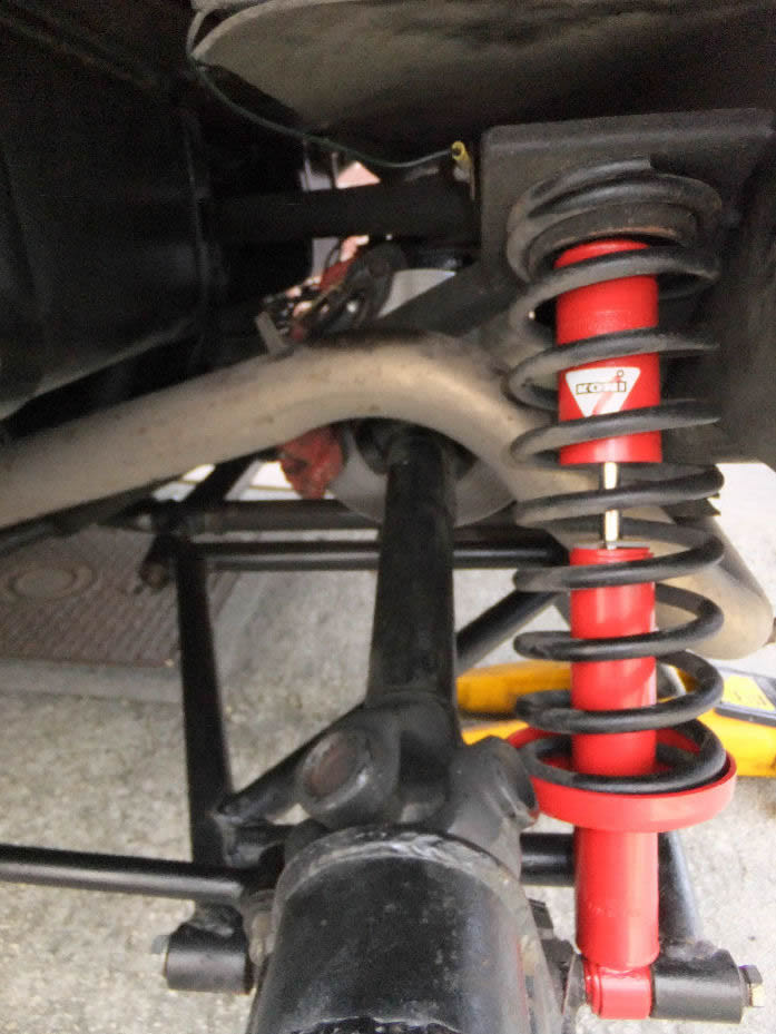
...and the spring/ damper assembly installed using good old compressors:
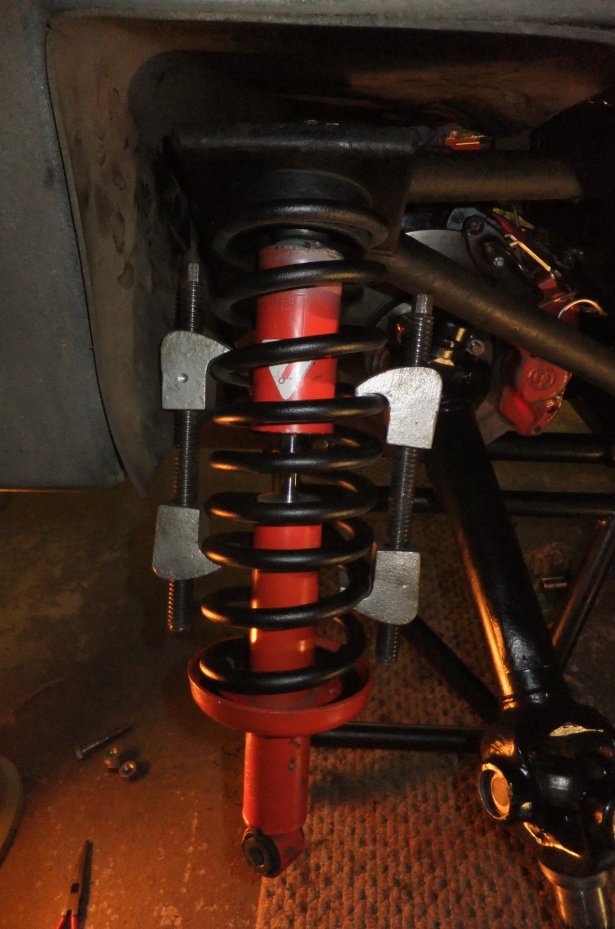
The top mounting is a bit fiddly but not as inaccessible as some folk make out:
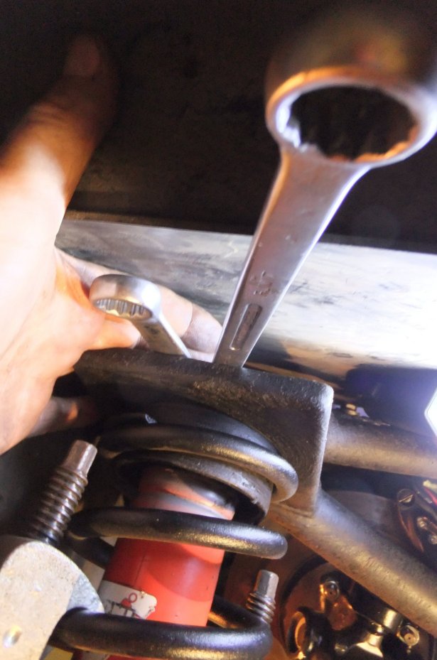
The wheel bearings had already been fitted to the hub carrier so it was just a case of slotting the carrier onto the stub axle, fitting the hub, washer and nut and installing a couple of bolts to tie the whole lot together...
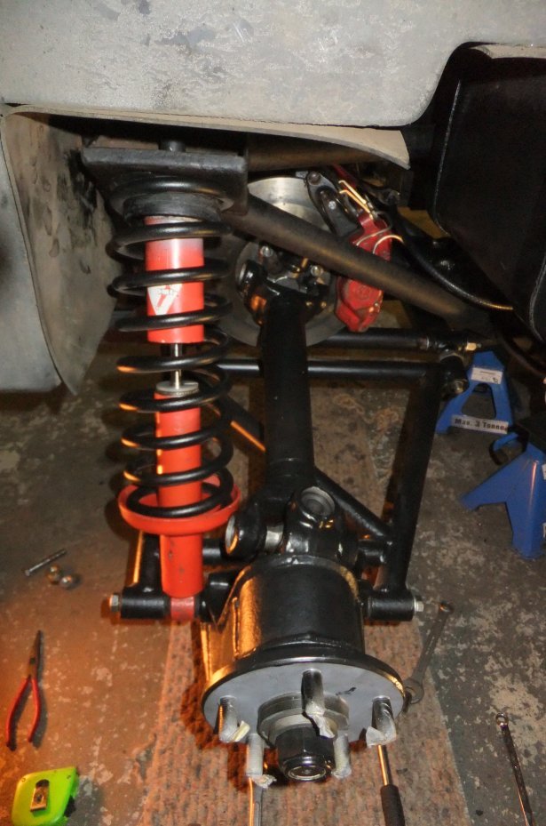
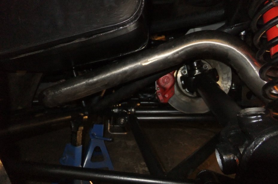
...including the forward tie-rod (again, pre-adjusted to about the length it was prior to removal):
Then I went round and rebuilt the other side!
The exhaust was wrestled into position...
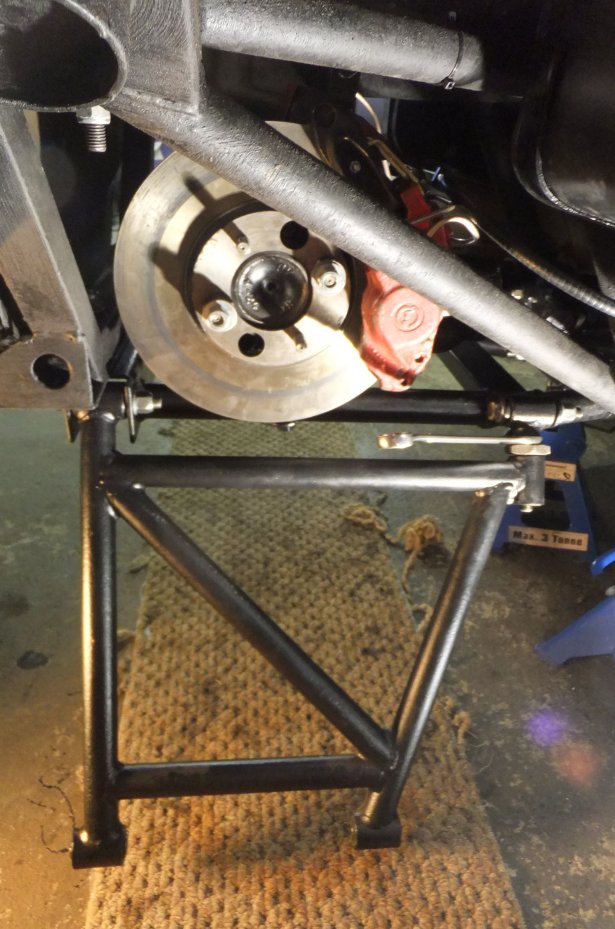
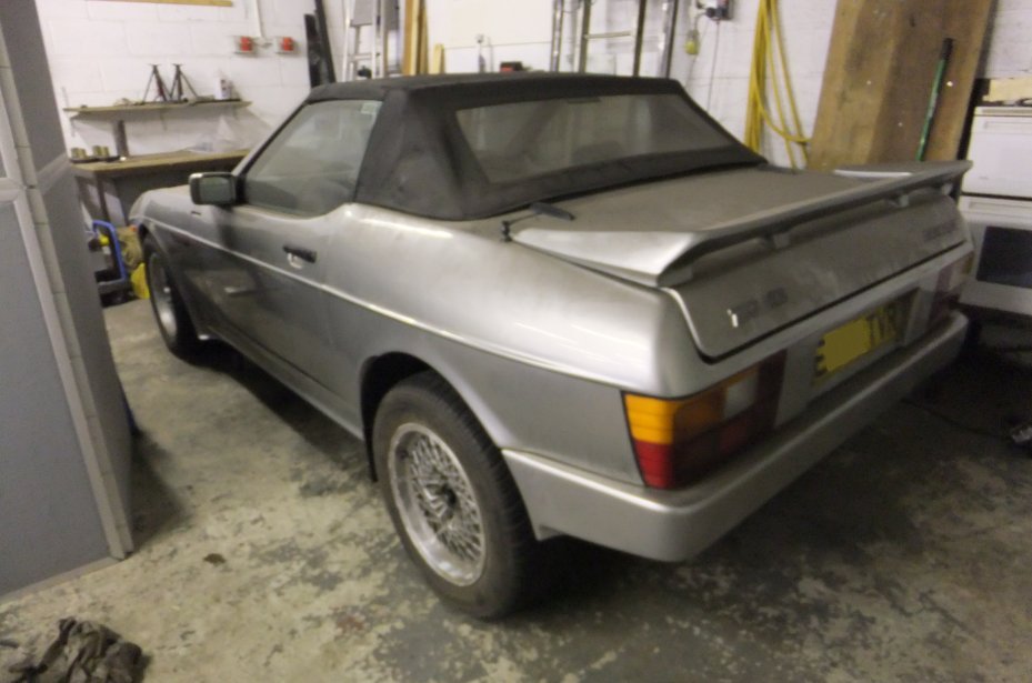
...and, just in time for New Year 2015, the (rather dusty) 390SE finally sat back on its wheels :^D
Needless to say that wasn't the end of the job: the brakes had to be fettled (including a modification to the handbrake, of which more later) but more importantly, after its long lay-up and being interested to hear what the repacked exhaust would sound like, the car 'needed' to be started. I'd noticed a coolant leak from somewhere around the thermostat housing and was worried that water might have found its way down into the sump so the car was jacked up and the engine oil drained, checked and refilled.
A few litres of fuel were tipped into the tanks and the rebuilt fuel system checked for leaks. The fuel pump relay was triggered to prime the system and the key turned. A few seconds of churning was rewarded with the familiar rumble and thud of the V8 which was allowed to warm up to operating temperature. A few experimental prods of the throttle proved that my silencer work had made very little difference to the sound of the exhaust, but on the plus side, it's no louder than it was before ;o)
Update April 2018
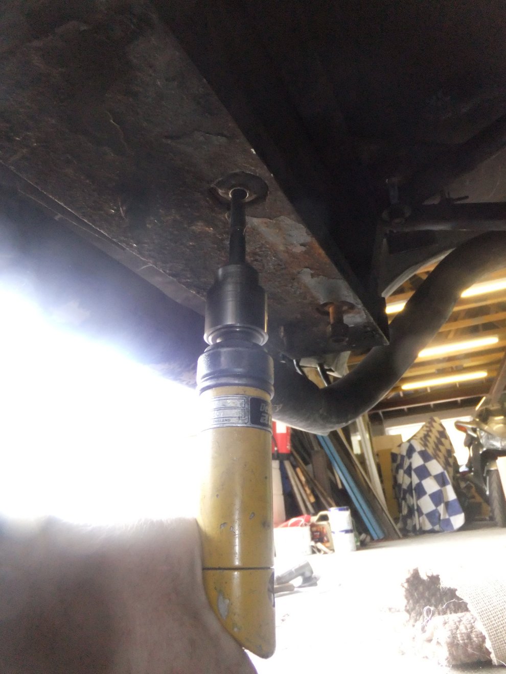
For no particular reason - i.e. the car hasn't moved in months and neither have I - as this year painfully claws its way out of winter I fought my way into the workshop and wondered what the hell I could be getting on with. As I opened a cupboard a rear suspension damper (see 4th photo down from top of page) fell out on my foot. I wasn't impressed. Then I remembered that ever since I rebuilt the back end (in the photo marathon above) I've been distinctly unimpressed with the ride quality. It was never brilliant but since the rebuild it's been decidedly crashy and I'm not sure where to point the finger of blame: is it the new Toyo tyres, a type I've never used before? Or the new suspension bushes I fitted, which are all rather less mushy than the old ones were after years of diff oil and lithium grease soaking them? Or how about those Koni dampers? They weren't the ones I took off before the rebuild, they were a pair I'd bought, blagged or been given some years before and when I compared them with the removed ones they seemed to be a better option for refitting (OK, OK, they were less rusty and more shiny :D). I'd tested the damping as far as I could (clamp in vice, pull and push damper through its range and see how smooth it is, then try the adjustment and see that it does actually adjust) and in all honesty I thought they were as good as, if not better than the removed pair. Some time back I'd contacted Koni UK and asked if they could supply a seal kit as these dampers are one of their rebuildable types, but although they offered to recondition them for me they wouldn't supply the bits so I could have a crack myself. Come on chaps, how hard can it be? Well, I think I've found the answer, because try as I might I can't undo the sealing plug in the top of the damper body. It requires a 2-pin spanner, which I didn't have, so I made one by welding two offcuts of 5mm steel plate together (to make it beefy) and then drilled and tapped in the appropriate places for a pair of 6mm high-tensile bolts, turned down in the lathe to leave a short length of plain shank that would engage the holes in the damper plug. I clamped the damper in the vice, applied the spanner and heaved. Nothing moved. So I tried a bit harder, then harder still, then I hit the spanner with a hammer, then I thought it might be a left-hand thread so I tried the other way. Nothing. I have a sectional drawing from Koni's catalogue that implies it's just a threaded plug, but I wondered if it might be drilled and pinned, so I taped up the damper rod and sandblasted the body around the plug so see if I could spot where it was pinned. Nothing. While I was contemplating my next move I sandblasted the rest of the damper. You can't fault the construction (well, at least not in those days, this one was made in 1992); Koni's claim that their dampers could outlast your car probably wasn't wrong! The damper rod's not pitted or bent, there's no oil leaking (I wiped the rod with a bit of tissue and it came away dry) and the spring seat is so thick it puts the bit of plate that TVR folded for the top seat to shame. Of course these dampers weigh more than my house as a result but you can't have it all ways. After heaving and clonking away for a while all I'd managed to do was elongate the pin holes and the spanner kept slipping out. In desperation I tried a pair of man-sized Stilsons on the bit of damper plug I could grip but apart from making it look like Jaws had been munching on it, there was still no movement. If Koni used an adhesive, it was a bloody good one. So at this point I gave up; after all the damper did seem to be working fine. I'll dig out the matching one, blast it and give them both a coat of paint (red, probably, although I could paint them bling-bling yellow and pretend they're from Koni's more expensive range :D) and swap them back onto the car for a comparison. When I get bored, have run out of other things to do (such as painting motorcycle bodywork, although that's another tale for another page on this site!). Now I think about it, I'm sure I bought a pair of the lower bushes some years back... as well as some Koni decals. All I need now is a paint that will cling on for another 26 years.
UPDATE 150718
As the weather has been distinctly un-British-summer-like for the last few weeks I decided to waste some money and put 6 months' tax on the 390. Then I realised that the MOT had expired a few weeks earlier. Bugger. A quick phone call to my tame local MOT place failed to get me a slot that day (it was a Saturday) so I've booked it in for next weekend (by which time the temperature will have dropped 15 degrees and it'll be raining sideways). In anticipation of the annual argument about the handbrake, I thought I'd drag the car out of the garage and wave some spanners... and with the air at 26 degrees that was a major undertaking, I can tell you! I'm a Northern Englishman: my operating range is -5 to +18 degrees :D Any lower and I have to wrap myself in a medium Rachel Riley, any more and I'm down to my budgie-smugglers and flaked out with a glass of something cold. I thought I'd go for the safe option of jacking the rear end and pulling a wheel off, rather than trying to reverse up the ramps. Then I remembered the Konis I'd blasted and painted a few weeks back and figured I may as well swap them while I was under there. So out with the spring compressors and a few spanners and the dampers were duly exchanged (note I found the new Koni decals - and also that my Fuji camera still can't work out what 'autofocus' means):
I was a shade disappointed (that's British understatement for you) to see that after the lengths I went to, preparing and repainting the chassis and suspension, the rust is bubbling merrily away despite the fact that the car has been hardly anywhere since and has spent most of its time under cover! The bloody paint seems to have evaporated altogether in places. Note to self: don't believe a word you read on paint tins. Anyway, the handbrake's adjusted, the dampers are swapped, fingers crossed nothing falls off before the MOT. I may even get to drive the thing this year... watch this space.
EDIT Oct' 19
Where does the bloody time go?! A couple of thousand more miles and I'm still not convinced either way that swapping the dampers made any difference. The car passed its MOT (and again this year) without any advisories; my tame MOT guy is about as old-school as you can get so understands that taper-roller front wheel bearings are supposed to have a bit of play and that Jaguar back brakes are crap :D For the most part then, this year has just been a driving year rather than a fettling year, but with only a few weeks of VED left to run the old bus will soon be settling down for another winter's slumbering.